Download
1 / 17
170 likes | 363 Vues
Calibration of I/P (current/Pressure) Honeywell Chapter 8. Honeywell Primer: Noise Environments. Presentation by Clifford T. Johnson, PE, Control Systems Engineer. Today. Instrumentation. ELC-213. Wire Function. wiring. Honeywell. ELC-213. Chapter AC Load Suppression. Suppression.

E N D
Calibration of I/P (current/Pressure) Honeywell Chapter 8 Honeywell Primer: Noise Environments Presentation by Clifford T. Johnson, PE, Control Systems Engineer Today Instrumentation ELC-213
Wire Function wiring Honeywell ELC-213
Chapter AC Load Suppression Suppression Honeywell ELC-213
AC Contact suppression Suppression Honeywell ELC-213
DC Suppression Suppression Honeywell ELC-213
I/P General Description I/P transducers are versatile instruments that use an electrical control signal to proportionally regulate gas pressure. The most common application is in valve actuation, but they can also be used in many other situations. As more processes become automated, I/P’s are being used more and more in place of manual regulators. Overall, I/P’s are relatively simple devices, but there are numerous factors to take into account before selecting one. The information that follows should provide you with a complete understanding of the factors involved in making the correct product selection, installation, and maintenance. When chosen, installed, and maintained correctly, I/P’s should provide many years of reliable service I/P Transducer ELC-213
I/P Principle of operation I/P Operation ELC-213
I/P Principle of operation I/P Operation ELC-213
I/P Accuracy The accuracy of an I/P transducer is defined in several ways. The most important measure is linearity. This is measured as a percent of span. In this case, the span is 12 (15 minus 3) psig. So if the linearity of the I/P was 1% of span, then the possible variation could be 1% of 12 or 0.12 psig. So in this case, the expected output with a 12mA signal. The output should be 9 psig but could be between 8.88 – 9.12 psig. Linearity can be as low as 0.1% and as high as 3% of span, depending on the construction and cost of the I/P. I/P Accuracy ELC-213
I/P Repeatability & Hysteresisis Repeatability measures the ability of the unit to come back to the same pressure setting after resetting the input signal. Hysteresisis is the variation in the output pressure achieved when increasing the input signal versus decreasing the input signal. For example, when going from 4 mA to 12mA a certain pressure will be attained. A different output pressure will be achieved when going from 20mA to 12 mA. I/P Accuracy ELC-213
Accuracies are additive Unless specified, these three measurements can be additive. Thus a 3-15 psig unit with +/- 1% linearity, +/- 1% Hysteresisis, +/- 1% repeatability, could be off by +/- 3%, or +/- .36 psig 3% span Accuracy Summary ELC-213
I/P Zero Calibration Always check the zero setting first. Apply the minimum electrical signal and observe the output pressure. It should be the minimum value of the pressure range. For example, a 4-20mA, 3-15 psig unit should give a 3 psig output at 4mA. If the output is not 3, turn the zero screw until the output pressure reaches 3. The screw may be turned in different directions depending on whether the unit is an I/P or E/P. I/P Calibration ELC-213
I/P Span Calibration Once the zero has been set, apply the maximum electrical signal, in this case, 20mA. The output should be close to the desired output, in this case 15 psig. Turn the span screw in the appropriate direction to achieve the desired pressure. Some I/P’s have interactive zero and span. In that case, after adjusting the span, the zero will need to be adjusted again, especially if the span was adjusted by a large amount. I/P Calibration ELC-213
I/P Media Supply The most common media for I/P’s is compressed air. They can also be used with many other inert gases. However, due to the constant consumption of the media, one must consider the environmental impact of the release of gas into the environment. You should definitely check the specifications before using the I/P with media other than compressed air. I/P Supply ELC-213
Use your Tag Calibration form I/P Cal Form ELC-213
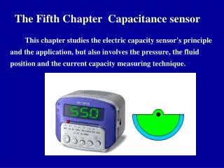
Calibration of Analyzers pH is one of the most difficult Analyzers to calibrate because the measurement is log pH Analyzer ELC-213
The End M-Systems I/P you will be calibrating End Calibration ELC-213