Analysis of CLP Voltage Trends Under Load Current and Power-Off Conditions
This report analyzes the behavior of the CLP voltage in response to varying load currents, specifically when the floating Vbat is set to 12V with a load current of 25mA. Key observations include the impact of the internal pull-up circuit allowing operation in low power and PWM modes, along with the persistent residual voltage on CLP and Cboot1 during power-off. The presence of a boost circuit prior to device shutdown aids voltage retention, resulting in steady CLP voltage reaching 5V in PWM mode. All findings are supported by bench test conclusions.

Analysis of CLP Voltage Trends Under Load Current and Power-Off Conditions
E N D
Presentation Transcript
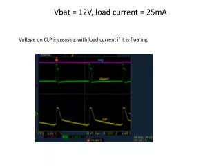
Voltage on CLP increasing with load current if it is floating Vbat = 12V, load current = 25mA
Power off behavior During power off residual voltage on CLP and Cboot1. All other pins have no residual voltage
Bench test conclusion • CLP has internal pull up circuit so device can operate in low power mode and PWM mode depends on load current • Floating CLP voltage is not because of crosstalk • CLP voltage can increase to 5V steady in PWM mode • During power down and before device turning off boost circuit is active • When device is off so Q3 transistor Cboot1 keeps residual voltage (see scope picture) • It seems the same amount of residual voltage in on CLP