Download
1 / 14
140 likes | 341 Vues
INSTABILITY OF ROTATING MAGNETIC FIELD DRIVEN FLOW IN A COUNTER-ROTATING CYLINDER. Alexander Pedchenko and Ilmars Grants Institute of Physics, University of Latvia, Salaspils, Latvia. PROBLEM FORMULATION. Applications of Rotating Magnetic Field (RMF). Continuous Casting of Steel,

E N D
INSTABILITY OF ROTATING MAGNETIC FIELD DRIVEN FLOW IN A COUNTER-ROTATING CYLINDER Alexander Pedchenko and Ilmars Grants Institute of Physics, University of Latvia, Salaspils, Latvia
PROBLEM FORMULATION Applications of Rotating Magnetic Field (RMF) Continuous Casting of Steel, Aluminum etc Semiconductor Crystal Growth melt mixing and homogenization stabilize unstable convective flow create variety of flows with different properties, combining mechanical and RMF induced rotation
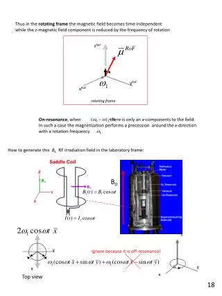
PROBLEM FORMULATION z side-wall boundary layer W instability may occur at high wRMF BRMF r W R r more stable flow RMF & counter-rotation driven flow wRMF ww-wRMF R ww
EXPERIMETAL SETUP Data Translation DT9821 4-channel 24-bit A/D USB module B 340 mm Nb-Fe-B magnets 40 mm • RMF Inductor • Container with liquid metal (Hg) • Permanent magnets • Rotating table with adjustable rot. speed • Registering equipment
EXPERIMETAL SETUP RMF coils Container with Hg RMF coils magnets Permanent magnets electrodes Registering equipment Rotating table SYSTEM PARAMETERS Container: H/R = 40/20 (mm) = 2 melt: Hg RMF: B = 0…3.8 mT (0≤Tam≤107) f = 45; 136 Hz Static magnetic field: [at z = H/2, r = 0] BSMF = 40 mT (Ha=20) Mechanical rotation: = 15 rpm (Rew=5500); = 45 rpm; (Rew=16500); Hg
EXPERIMETAL RESULTS: Container at rest P.A.Davidson formula * for turbulent flow numerical simulation w/ DC field calibration of electrodes by applying abrupt pulse of mechanical rotation y = f (Wc) - ? spin-down of fluid numerical simulation w/o DC field stable rotation of fluid experiment RMF freq 45Hz spin-up of fluid experiment RMF freq 136Hz * Wc=1.98(n/Ro2)Ta5/9 P.A.Davidson, JFM 245, 1992 Determination of the fluid rotation rate driven by RMF only:
EXPERIMETAL RESULTS: Container at rest Fluctuating component of the registered electric potential for different strengths of RMF
EXPERIMETAL RESULTS: = 2.3 ×10⁶ (2.4 mT) = 0.23 ×10⁶ (0.75 mT) = 0.45 ×10⁶ (1.1 mT) c m Ta c m c Ta m Ta w = 0 w = - 15 rpm w = - 45 rpm Intensity of fluctuations (dy) vs. magnetic forcing (Tam) Ta = swoBo2Ro4/2rn2 s - electrical conductivity wo - RMF frequency Bo - RMF induction Ro - container radius r - density of the fluid n - kinematical viscosity 1 dy, mV 0.1 0.01 5 6 7 10 10 10 Ta m
NUMERICAL STUDY: • f (r,z) - e.m. force • wo - RMF frequency • Bo - RMF induction • - rotation rate of cavity Ro - radius of cavity • - viscosity r - density (r,f,z,t) - flow velocity; = 0 Boundary conditions: where: Steady axisymmetric solution o (r, z) is linearly unstable to infinitesimal perturbations ’ (r, f, z) when an eigenvalue problem with ’ = 0 and has at least one eigenvalue lr > 0
NUMERICAL RESULTS: Calculation with SMF Experiment Flow reversal Ta values Tac (Rew) calc. Rew3/2
NUMERICAL RESULTS: Rew= 200 Rew= 250 Rew= 300 ~ exp(lr+ilI)t t l r 5 Ta/10
NUMERICAL RESULTS: Ta = 1.5×10⁴ Wc< 0 (wall direction) Wc= 0 Azimuthal flow Wc> 0 (RMF direction) axial coordinate -1 0 1 Meridional flow radial coordinate
side-wall boundary layer W instability may occur at high wRMF r R more stable flow Still stable flow unstable flow Conclusions wRMF ww-wRMF ww
Conclusions • Concurrent action of RMF and mechanical counter-rotation on the instability onset in cylindrical container with aspect ratio H/R=2 observed experimentally and numerically • Strong counter-rotation of the container stabilizes the flow driven by RMF and changes the direction of the meridional circulation • Weak counter-rotation of the container (when the RMF driven rotation is comparable to the rotation of the container) destabilize the flow. Concentration of the differential swirl occurs near the axis and Rayleigh stability criterion violated in this area. • Regime with rapid instability can be used in applications when additional stirring of the melt is required e.g casting of metals etc.