### Design and Implementation of an Autonomous UAV for International Aerial Robotics Competition ###
130 likes | 253 Vues
This project outlines the development of an autonomous Unmanned Aerial Vehicle (UAV) for the International Aerial Robotics Competition. The UAV will feature advanced systems for stability, obstacle avoidance, and extensibility for future upgrades such as SLAM and vision processing. The design incorporates a complex control system including motor controllers, sensors, and communication systems powered by a high-capacity LiPo battery. Testing will focus on stability under external disturbances, communication reliability, flight control accuracy, and obstacle avoidance effectiveness, ensuring robust performance in competition scenarios. ###

### Design and Implementation of an Autonomous UAV for International Aerial Robotics Competition ###
E N D
Presentation Transcript
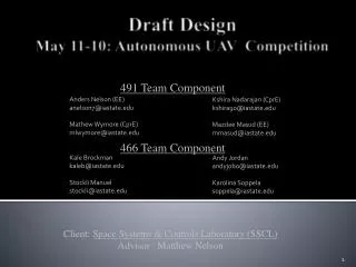
Client: Space Systems & Controls Laboratory (SSCL) Advisor : Matthew Nelson 491 Team Component Anders Nelson (EE) anelson7@iastate.edu Mathew Wymore (CprE) mlwymore@iastate.edu Kale Brockman kaleb@iastate.edu StockliManuel stockli@iastate.edu KshiraNadarajan (CprE) kshira90@iastate.edu MazdeeMasud (EE) mmasud@iastate.edu Andy Jordan andyjobo@iastate.edu Karolina Soppela soppela@iastate.edu Draft Design May 11-10: Autonomous UAV Competition 466 Team Component
Unmanned Aerial Vehicle • International Aerial robotics Competition – AUVSI • Autonomous flying robot • Stability, obstacle avoidance • Extensible for future development – SLAM, vision etc. Source: AUVSI. International Aerial Robotics Competition. Retrieved on 11/14/2010 from http://iarc.angel-strike.com/index.php.
System Decomposition • Control System • Main controller • Motor controller • Sensor System • Inertial Measurement Unit (IMU) • Cameras, Range Finders • Will not be selected by us. • Communications System • Software System • Power System
Control System • Main Controller (GumstixOvero) • USB Host stack (laser) • I2C (motor controller) • Linux (ease of use) • Motor controller (16-bit PIC) • Serial I/O (IMU) • PWM out (ESCs) • I2C (main controller)
Software System • Positioning System • Issues commands to motion controller • Motion Control and Heading*: • Acquires commands from positioning system • Translates commands to motor signals • Obstacle avoidance module: • Reads current sensor data • Identifies immediate obstacles and avoids them *Process marked in Red indicates implementation in motor controller rather than main controller
Sensor System • Inertial Measurement Unit (IMU) • Takes in 9 DOF measurements • Outputs to Motor Microcontroller through serial interface • External Sensors • IR/sonar sensors • For basic obstacle avoidance • Used as a fail safe for navigation system • Range Finders and Vision Systems • To be selected by later teams for SLAM
Communications System • RF System • WiFi integrated into main controller • Base station communication • RC Hobby System • Allows manual control • Comes into motor controller
Power System • LiPo Battery • 11.1V • 6000 ~ 6500 mAh • 20 C Maximum (Continuous Discharging) • 3 Cell • Serial Connection • 11.1V (Combination of three single cell/one single & one 2 cell battery) • 6000 ~ 6500 mAh/cell • 20 C Maximum • Parallel Connection • 11.1 V/cell • 6000 ~ 6500 mAh (Combination of three single cell/one single & one 2 cell battery) • 20 C Maximum
Test Plan • Stability • Test motor stability control with varying degrees of external disturbance and record response • Communication • Test distance and speed of communication between platform and remote base • Flight Control • Determine accuracy of movement from various control commands • Obstacle Avoidance • Determine reliability and accuracy of obstacle avoidance from movement in various directions • Endurance (Power) • Will run the battery under expected load while monitoring voltage over time