Iowa State University
320 likes | 490 Vues
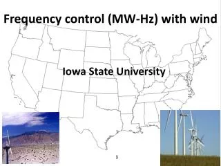
Iowa State University. Frequency control (MW-Hz) with wind. Outline. MW-Hz time frames Transient frequency control Frequency governing CPS1, CPS2 Simulations Solutions Conclusions. MW-Hz Time Frames. 0+<t<2s; Inertial. 10s<t<5m; AGC. 2s<t<10s; Speed-governors. 5m, ED.

Iowa State University
E N D
Presentation Transcript
Iowa State University Frequency control (MW-Hz) with wind
Outline MW-Hz time frames Transient frequency control Frequency governing CPS1, CPS2 Simulations Solutions Conclusions
MW-Hz Time Frames 0+<t<2s; Inertial 10s<t<5m; AGC 2s<t<10s; Speed-governors 5m, ED t=0+; Proximity
MW-Hz Time Frames This is load decrease, shown here as a gen increase. Source: FERC Office of Electric Reliability available at: www.ferc.gov/EventCalendar/Files/20100923101022-Complete%20list%20of%20all%20slides.pdf
= + Load Following Regulation MW-Hz Time Frames Source: Steve Enyeart, “Large Wind Integration Challenges for Operations / System Reliability,” presentation by Bonneville Power Administration, Feb 12, 2008, available at http://cialab.ee.washington.edu/nwess/2008/presentations/stephen.ppt.
What can happen if frequency dips too low? • For f<59.75 Hz, underfrequency relays can trip load. • For f<59 Hz, loss of life on turbine blades • Violation of NERC criteria with penalties • N-1: Frequency not below 59.6 Hz for >6 cycles at load buses • N-2: Frequency not below 59.0 Hz for >6 cycles at load buses Transient frequency control
Transient frequency control The greater the rate of change of frequency (ROCOF) following loss of a generator ∆PL, the lower will be the frequency dip. ROCOF increases as total system inertia ΣHi decreases. Therefore, frequency dip increases as ΣHi decreases.
2.75 sec Nadir 49.35 Example: Ireland: ∆PL =432 MW=4.32 pu. ΣHi =475 sec Transient frequency control 1. Governors 2. Load frequency sensitivity 50-0.227*2.75=49.38Hz
Nadir 59.9828 Hz 59.9725z Example: Estrn Interconnection: ∆PL =2900 MW=29 pu. ΣHi =32286 sec Transient frequency control 60-0.0269*1.5=59.9597Hz
So what is the issue with wind….? Increasing wind penetrations tend to displace (decommit) conventional generation. DFIGs, without specialized control, do not contribute inertia. This “lightens” the system (decreases denominator) Transient frequency control Let’s see an example….
Transient frequency control • Green: Base Case • Dark Blue: 2% Wind Penetration • Light Blue: 4% Wind Penetration • Red: 8% Wind Penetration Estrn Interconnection: Frequency dip after 2.9GW Gen drop for Unit De-Commitment scenario atdifferent wind penetration levels (0.6, 2, 4, 8%)
Fuel supply control Steam valve control Generator Steam Boiler FUEL MVAR-voltage control STEAM-TURBINE CONTROL SYSTEM Generator Gear Box Wind speed Real power output control MVAR-voltage control WIND-TURBINE CONTROL SYSTEM Why do DFIGs not contribute inertia? They do not decelerate in response to a frequency drop. Transient frequency control The ability to control mech torque applied to the generator using pitch control & electromagnetic torque using rotor current control (to optimize Cp and to avoid gusting) enables avoidance of mismatch between mechanical torque and electromagnetic torque and, therefore, also avoidance of rotor deceleration under network frequency decline.
What is the fix for this? Consider DFIG control system Transient frequency control Source: J. Ekanayake, L. Holdsworth, and N. Jenkins, “Control of DFIG Wind Turbines,” Proc. Instl Electr. Eng., Power Eng., vol. 17, no. 1, pp. 28-32, Feb 2003.
Add “inertial emulation,” a signal dω/dt scaled by 2H Transient frequency control -2H dω / dt
Several European grid operators have imposed requirements on wind plants in regards to inertial emulation, including Nordic countries [1,2]. North American interconnections have so far not imposed requirements on wind farms in regards to frequency contributions, with the exception of Hydro-Quebec. The Hydro-Quebec requirement states [3, 4], “The frequency control system must reduce large, short-term frequency deviations at least as much as does the inertial response of a conventional generator whose inertia (H) equals 3.5 sec.” Transient frequency control [1] “Wind Turbines Connected to Grids with Voltages above 100 kV – Technical Regulation for the Properties and the Regulation of Wind Turbines, Elkraft System and Eltra Regulation, Draft version TF 3.2.5, Dec., 2004. [2] “Nordic Grid Code 2007 (Nordic Collection of Rules), Nordel. Tech. Rep., Jan 2004, updated 2007. [3] N. Ullah, T. Thiringer, and D. Karlsson, “Temporary Primary Frequency Control Support by Variable Speed Wind Turbines – Potential and Applications,” IEEE Transactions on Power Systems, Vol. 23, No. 2, May 2008. [4] “Technical Requirements for the Connection of Generation Facilities to the Hydro-Quebec Transmission System: Supplementary Requirements for Wind Generation,” Hydro Quebec, Tech. Rp., May 2003, revised 2005.
Frequency Governing Characteristic, β β, “If Beta were to continue to decline, sudden frequency declines due to loss of large units will bottom out at lower frequencies, and recoveries will take longer.” Source: J. Ingleson and E. Allen, “Tracking the Eastern Interconnection Frequency Governing Characteristic,” Proc. of the IEEE PES General Meeting, July 2010.
Fossil-steam plant changes, motivated to increasing economic efficiency: • Use of larger governor deadband settings, exceeding the historical typical setting of ±36 millihertz (mHz); • Use of steam turbine sliding pressure controls; • Loading units to 100 percent of capacity leaving no “headroom” for response to losses of generation; • Blocked governor response (nuclear licensing may also cause this); • Use of once-through boilers; • Gas Turbine inverse response; • • Changes in the frequency response characteristics of the load: • Less heavy manufacturing, therefore less induction motor load • More speed drives which may reduce frequency sensitivity of induction motors Reasons for decrease in β “These changes have been evolving for some time and are not the direct result of the emergence of renewable resources such as wind and solar.” Source: “Comments Of The North American Electric Reliability Corporation Following September 23 Frequency Response Technical Conference,” Oct. 14, 2010. See www.ferc.gov/EventCalendar/EventDetails.aspx?ID=5402&CalType=%20&CalendarID=116&Date=09/23/2010&View=Listview
Wind is small now, so the NERC comment that decreasing β is not due to wind is correct, but…this will not be true if, at higher wind penetrations, non-wind units with speed governing are displaced with wind units without speed governing. Decreasing β will risk violation of NERC Standard BAL-001-0.1a — Real Power Balancing Control Performance Two Comments • Each Balancing Authority shall achieve, as a minimum, • Requirement 1: CPS1 compliance of 100% • Requirement 2: CPS2 compliance of 90% • and $ penalties apply for non-compliance. So what are CPS1 and CPS2? Ref: N. Jaleeli and L. Van Slyck, “NERC’s New Control Performance Standards,” IEEE Transactions on Pwr Systems, Vol 14, No 3, Aug 1999.
CPS1 is a measure of a balancing area’s long term (12 month) frequency performance. The targeted control objective underlying CPS1 is to bound excursions of 1-minute average frequency error over 12 months in the interconnection. As the interconnection frequency error is proportional to the sum of all balancing areas’ ACEs, maintaining averages of ACEs within proper statistical bounds will therefore maintain the corresponding averages of frequency error within related bounds. With the interconnection frequency control responsibilities being distributed among balancing areas, CPS1 measures control performance by comparing how well a balancing area’s ACE performs in conjunction with the frequency error of the interconnection. ε1 is maximum acceptable steady-state freq deviation- 0.018Hz in east interconnection.
CPS1 If ACE is positive, the control area will be increasing its generation, and if ACE is negative, the control area will be decreasing its generation. If ∆F is positive, then the overall interconnection needs to decrease its generation, and if ∆F is negative, then the overall interconnection needs to increase its generation. Therefore if the sign of the product ACE×∆F is positive, then the control area is hindering the needed frequency correction, and if the sign of the product ACE×∆F is negative, then the control area is contributing to the needed frequency correction. The minimum score of CPS1 compliance is 100%. If an area has a compliance of 100%, they are supplying exactly the amount of frequency support required. Anything above 100 is “helping” interconnection frequency whereas anything below 100 is “hurting” interconnection frequency.
CPS2is a measure of a balancing area’s ACE over all 10-minute periods in a month. The control objective is to bound unscheduled power flows between balancing areas. It was put in place to address the concern that a balancing area could grossly over- or under-generate (as long as it was opposite the frequency error) and get very good CPS1, yet impact its neighbors with excessive flows. • Num(.) denotes “number of times that…” over 1 month. • (ACE) 10min is the 10 min average of ACE • L10 describes the interval within which |(ACE) 10min| • should be controlled. • BS=sum of B values for all control areas. • ε10 =targeted 10-minute average frequency error bound for Interconnection
Simulation System • Two Area System (Area A and Area B) • Wind power is assumed in area A • Each area consists of 10 conventional units, with inertia and with speed governing • 24 hour UC is run based on a load and wind forecast • Wind penetration levels- 6%, 10%, 25%, and 31% (Pw/Pnw) are considered (by capacity), without inertia or speed governing (would be 5, 9, 20, 24% Pw/(Pw+Pnw)). • Wind is assumed to displace conventional units • Actual sec-by-sec p.u. value of load and of wind power data from one wind farm is used. A B Con Con Wind
Simulation Results Conclusion: Wind degrades frequency performance due to inertia, no control, and variability. These 3 issues need to be and can be addressed.
Fuel supply control Steam valve control Generator Steam Boiler FUEL MVAR-voltage control STEAM-TURBINE CONTROL SYSTEM Generator Gear Box Wind speed Real power output control MVAR-voltage control WIND-TURBINE CONTROL SYSTEM Regulation via rotor speed & pitch control Pitch control Rotor speed control Rotor speed control is well suited for continuous, fine, frequency regulation; blade pitch control provides fast acting, coarse control both for frequency regulation as well as emergency spinning reserve. Sources: Rogério G. de Almeida and J. A. Peças Lopes, “Participation of Doubly Fed Induction Wind Generators in System Frequency Regulation,” IEEE Trans On Pwr Sys, Vol. 22, No. 3, Aug. 2007. B. Fox, D. Flynn, L. Bryans, N. Jenkins, D. Milborrow, M. O’Malley, R. Watson, and O. Anaya-Lara, “Wind Power Integration: Connection and system operational aspects,” Institution of engineering and technology, 2007.
Manufacturers & some wind farms have it See http://www.gepower.com/prod_serv/products/wind_turbines/en/downloads/wind_plant_perf2.pdf. Then why don’t they use it?
Review of the websites from TSOs (in Europe), reliability councils (i.e., NERC and regional organizations) and ISOs (in North America) suggest that there are no hard requirements regarding use of primary frequency control in wind turbines. • There are soft requirements [1]: • BCTC will specify “on a site by site basis,” • Hydro Quebec requires that wind turbines be “designed so that they can be equipped with a frequency control system (>10MW)” • Manitoba Hydro “reserves the right for future wind generators” Regulation via rotor speed & pitch control NERC [2], said, “Interconnection procedures and standards should be enhanced to address voltage and frequency ride-through, reactive and real power control, frequency and inertial response and must be applied in a consistent manner to all generation technologies.” [1] “Wind Generation Interconnection Requirements,” Technical Workshop, November 7, 2007, available at www.bctc.com/NR/rdonlyres/13465E96-E02C-47C2-B634-F3BCC715D602/0/November7WindInterconnectionWorkshop.pdf. [2] [North American Electric Reliability Corporation, “Special Report: Accommodating High Levels of Variable Generation,” April 2009, available at http://www.nerc.com/files/IVGTF_Report_041609.pdf.
ERCOT says [1], “…as wind generation becomes a bigger percentage of the on line generation, wind generation will have to contribute to automatic frequency control. Wind generator control systems can provide an automatic response to frequency that is similar to governor response on steam turbine generators. The following draft protocol/operating guide concept is proposed for all new wind generators: All WGRs with signed interconnect agreements dated after March 1, 2009 shall have an automatic response to frequency deviations. …” Regulation via rotor speed & pitch control [15] Draft White Paper, “Wind Generation White Paper: Governor Response Requirement,” Feb, 2009, available at www.ercot.com/content/meetings/ros/keydocs/2009/0331/WIND_GENERATION_GOVERNOR_RESPONSE_REQUIREMENT_draft.doc..
Increase control of the wind generation • Provide wind with inertial emulation & speed governing • Limit wind generation ramp rates • Limit of increasing ramp is easy to do • Limit of decreasing ramp is harder, but good forecasting can warn of impending decrease and plant can begin decreasing in advance • Increase non-wind MW ramping capability during periods of expected high variability using one or more of the below: • Conventional generation • Load control • Storage Solutions to degraded frequency performance • Steam turbine plants 1- 5 %/min • Nuclear plants 1- 5 %/min • GT Combined Cycle 5 -10 %/min • Combustion turbines 20 %/min • Diesel engines 40 %/min
12 400 100 60.04 HUNTVILL Wind Power With Storage Wind plant 10 80 350 NANTCOKE CAES Power 60.03 No Storage Hybrid Wind Systems HOLDEN REDBRIDG CHENAUX CHFALLS MARTDALE NaS Battery Power ×10 60 300 8 60.02 Wind Speed (s) 40 250 LAKEVIEW 6 60.01 BRIGHTON CEYLON RICHVIEW STINSON 20 Power Command (MW) PICTON Mismatch (MW) 200 System Frequency (Hz) 4 HEARN 0 60 150 -20 WALDEN COBDEN MTOWN 59.99 2 MITCHELL KINCARD HANOVER 100 0 200 400 600 800 1000 1200 1400 1600 1800 -40 Time (s) 59.98 50 -60 BVILLE PARKHILL DOUGLAS GOLDEN JVILLE STRATFRD 59.97 0 -80 WVILLE 59.96 -100 -50 0 200 400 600 800 1000 1200 1400 1600 1800 0 0 200 200 400 400 600 600 800 800 1000 1000 1200 1200 1400 1400 1600 1600 1800 1800 Time (S) Time (s) Hybrid Wind Systems – Save Money, Enhance Frequency Regulation Life time: 20 years
First, primary frequency control for over-frequency conditions, which requires generation reduction, can be effectively handled by pitching the blades and thus reducing the power output of the machine. Although this action “spills” wind, it is effective in providing the necessary frequency control. Second, primary frequency control for under-frequency conditions requires some “headroom” so that the wind turbine can increase its power output. This means that it must be operating below its maximum power production capability on a continuous basis. This also implies a “spilling” of wind. Question: Should we “spill” wind in order to provide frequency control, in contrast to using all wind energy and relying on some other means to provide the frequency control? Answer: Need to compare system economics between increased production costs from spilled wind, and increased production and investment costs from using storage and conventional generation. How to decide?