Nozzle Study
Nozzle Study. Yan Zhan, Foluso Ladeinde April , 2011. Outlines. Region of interests Bend Combinations without nozzle Bend Combinations Without Nozzle Turbulence Model Comparisons Mercury Flow in Curved Pipes Discussions Bend Combinations with Nozzle Bend Combinations With Nozzle

Nozzle Study
E N D
Presentation Transcript
Nozzle Study Yan Zhan, FolusoLadeinde April , 2011
Outlines • Region of interests • Bend Combinations without nozzle • Bend Combinations Without Nozzle • Turbulence Model Comparisons • Mercury Flow in Curved Pipes • Discussions • Bend Combinations with Nozzle • Bend Combinations With Nozzle • Mercury Flow in Curved Nozzle Pipes • Discussions • Appendix
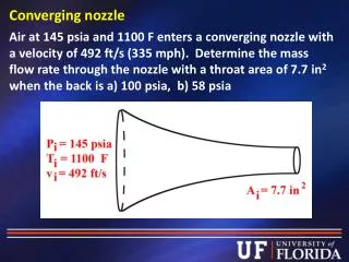
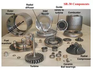
Region of interests • Interests: Influence of nozzle • & nozzle upstream on the jet exit Simulation Regime Hg delivery system at CERN
Outlines • Region of interests • Bend Combinations without nozzle • Bend Combinations Without Nozzle • Turbulence Model Comparisons • Mercury Flow in Curved Pipes • Discussions • Bend Combinations with Nozzle • Bend Combinations With Nozzle • Mercury Flow in Curved Nozzle Pipes • Discussions • Appendix
Bend Combinations Without Nozzle (1) Mesh at the cross-section nr × nθ=152×64 (the 1st grid center at y+≈1) Geometry of bends with varying angles Nondimensionalized by pipe diameter (p.d.); φ range: 0⁰, 30⁰, 60⁰, 90⁰.
Bend Combinations Without Nozzle (2) (a) (c) (b) (d) Geometries without nozzle: (a) 0⁰/0⁰ ; (b) 30⁰/30⁰; (c) 60⁰/60⁰; (d) 90⁰/90⁰ nx=40 +nφ+20+ nφ +100 where nφ depends on the bend angle φ
Turbulence Model Comparisons (2) Sudo’s Experiment (1998) for 90⁰ bend* uave = 8.7 m/s; Re=6×10⁴; ρair = 1.2647; μair = 1.983×10⁻⁵; Pr= 0.712 • K. Sudo, M. Sumida, H. Hibara, 1998. Experimental investigation on turbulent flow in a circular-sectioned 90-degrees • bend, Experiments in Fluids. 25, 42-49.
Turbulence Model Comparisons (3) Inlet nφ =75 (dφ=1.2⁰) Outlet Upstream: n’=375 Downstream: n=150 Mesh for the test pipe Mesh at the cross-section nr × nθ=80×50 (the 1st grid center at y+≈1)
Turbulence Model Comparisons (4) Longitudinal distribution of wall static pressure Cp pressure coefficient pref reference value of p at z’/d=-17.6 RKεis the best of the three in simulating curved pipe flow
Mercury Flow in Curved Pipes (1) • Steady incompressible turbulent flow • Boundary Conditions • Inlet: Fully developed velocity; • Outlet: Outflow; • Wall: non-slip • Schemes • 3rd order MUSCL for momentum and turbulence equations • SIMPLE schemes for pressure linked equations • Convergence Criterion • 10-5
Mercury Flow in Curved Pipes (2) • Turbulence Characteristics • Turbulence Level (Flutuating Velocity) • Momentum Thickness (Mean Velocity) Measure of the momentum loss within the boundary layer due to viscosity. Small I Big θt
Mercury Flow in Curved Pipes (3) • Turbulence Level (1) Fig. Two shown planes at the pipe outlet Table. Mean turbulence level at pipe outlet Mean Iin=4.600041%
Mercury Flow in Curved Pipes (4) • Turbulence Level (2) (a) (b) • Turbulence intensity distribution at the pipe exit • Horizontal plane (from inner side to outer side ) • Vertical (from bottom to top )
Mercury Flow in Curved Pipes (4) • Momentum Thickness Momentum thickness distribution along the wall at the pipe exit (a) 0⁰/0 ⁰ bend (b)30⁰/30 ⁰ bend (c) 60⁰/60 ⁰ bend (d) 90⁰/90 ⁰ bend
Discussions • Bend Effects • Bend and turbulence level • Bend enhances the turbulence level but not too much; • The 0⁰/0⁰ bend has the lowest turbulence level; • Symmetry I for the 90⁰/90⁰ bend; • Bend and θt • Bend effects θt not linearly with the increasing bends • The 60⁰/60⁰ bend seems likea turning point • Less uniform θt distribution in larger bend • θt is bigger near the inner side and smaller near the outer side
Outlines • Region of interests • Bend Combinations without nozzle • Bend Combinations Without Nozzle • Turbulence Model Comparisons • Mercury Flow in Curved Pipes • Discussions • Bend Combinations with Nozzle • Bend Combinations With Nozzle • Mercury Flow in Curved Nozzle Pipes • Discussions • Appendix
Bend Combinations With Nozzle Mesh at the cross-section (half model) nr × nθ=152×64 (the 1st grid center at y+≈1) Geometry of bends with varying angles Nondimensionalized by pipe diameter (p.d.); φ range: 0⁰, 30⁰, 60⁰, 90⁰.
(a) (b) (c) (d) Mesh for bends (a) 0⁰/0⁰ ; (b) 30⁰/30⁰; (c) 60⁰/60⁰; (d) 90⁰/90⁰ nx=40 +nφ+20+ nφ +60+70 where nφ depends on the bend angle φ
Mercury Flow in Curved Nozzle Pipes (1) Longitudinal distribution of static pressure for 90⁰/90⁰ Combination Velocity inlet condition Pin 30bar; uin fully developed velocity profile; Outlet flow condition
Mercury Flow in Curved Nozzle Pipes (2) • Main Loss Assume smooth pipe, thus Pmain=0 • Minor Loss • Elbow Loss • Contraction Loss • Total Loss
Mercury Flow in Curved Nozzle Pipes (3) • Bernoulli’s Law • Comparison
Mercury Flow in Curved Nozzle Pipes (4) • Turbulence Level (1) Fig. Two shown planes at the pipe outlet Table. Mean turbulence level at pipe outlet Mean Iin=4.599195%
Mercury Flow in Curved Nozzle Pipes (5) • Turbulence Level (2) (a) (b) Turbulence intensity distribution at the pipe exit Horizontal plane ; (b) Vertical plane
Mercury Flow in Curved Pipes (6) • Momentum Thickness Momentum thickness distribution along the wall at the pipe exit (a) 0⁰/0 ⁰ bend (b)30⁰/30 ⁰ bend (c) 60⁰/60 ⁰ bend (d) 90⁰/90 ⁰ bend
Discussions (1) (b) (a) Turbulence intensity distribution at the pipe exit Horizontal plane (b)Vertical plane
Discussions (2) The comparison of momentum thickness distribution at the pipe exit between pipe with/without nozzle (a) 0⁰/0 ⁰ bend (b)30⁰/30 ⁰ bend (c) 60⁰/60 ⁰ bend (d) 90⁰/90 ⁰ bend Red: pipe without nozzle; Blue: pipe with nozzle.
Discussions (3) • Nozzle Effects • Nozzle and turbulence level • Nozzle reduces the turbulence level; • The 90⁰/90⁰ bend doesn’t change too much; • I of the 90⁰/90⁰ bend is far different from other bends • Nozzle and θt • Nozzle decreases θt • Very uniform and similar θt distribution at the nozzle exit for all bend pipes
Outlines • Region of interests • Bend Combinations without nozzle • Bend Combinations Without Nozzle • Turbulence Model Comparisons • Mercury Flow in Curved Pipes • Discussions • Bend Combinations with Nozzle • Bend Combinations With Nozzle • Mercury Flow in Curved Nozzle Pipes • Discussions • Appendix
Appendix(1) • Continuity Equation The two-phase model considers mixture comprising of liquid, vapor and non-condensable gas (NCG). Gas is compressible, the liquid and vapor are impressible. The mixture is modeled as incompressible. • Momentum Equations
Appendix(2) • Spalart-Allmaras Model
Appendix(3) • Turbulent Viscosity (SA)
Appendix (4) • Standard K-ε model
Appendix (5) • Turbulent Viscosity (SKε)
Appendix (6) • Realizable K-ε model
Appendix (7) • Turbulent Viscosity (RKε)
Appendix (9) • Properties of fluid • Steady incompressible turbulent flow