Download
1 / 12
150 likes | 427 Vues
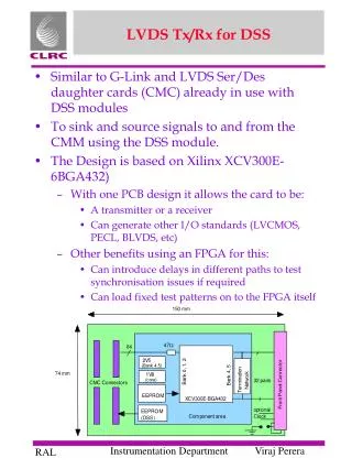
Universal LVDS ribbon cable. Marc Defossez 12 th December 2005. Generic Schematic Symbol. CLK / Sync / IO. CLK / Sync / IO. IO. IO. IO. IO. IO. IO. IO. IO. IO. IO. IO. IO. PCB mounted QSE part. QSE / QTE –028-01-L-D-DP-A. IO. IO. IO. IO. IO. IO. IO. IO. IO. IO. IO.

E N D
Universal LVDS ribbon cable Marc Defossez 12th December 2005
Generic Schematic Symbol CLK / Sync / IO CLK / Sync / IO IO IO IO IO IO IO IO IO IO IO IO IO PCB mounted QSE part QSE / QTE –028-01-L-D-DP-A IO IO IO IO IO IO IO IO IO IO IO IO CLK / Sync / IO CLK / Sync / IO
Schematic Symbol • This represents a ground connection. • These pins are physically not available on a differential pair QSE / QTE Samtec connector. • They are available when using the standard type QSE or QTE connectors. • Represented with the ground connections is the middle-connector ground plane.
QSE / QTE –028-01-L-D-DP-A- XLVDS Schematic Symbol Tranmitter PCB side. Due to the symmetry of the cable, both connectors can not be placed the same way. The receiver side of the connector can be found on next page. N N CLK Sync P P 15 14 N N P P 13 12 N N P P 11 10 N N P P 9 8 N N P P 7 6 N N P P 5 4 N N P P 3 N N 2 P P 1 0 N N P P nc nc PCB mounted QSE part nc nc nc nc nc nc nc nc
QSE / QTE –028-01-L-D-DP-A- XLVDS Schematic Symbol N N Receiver PCB side. Due to the symmetry of the cable, both connectors can not be placed the same way. The transmitter side of the connector can be found on previous page. CLK Sync P P 15 14 N N P P 13 12 N N P P 11 10 N N P P 9 8 N N P P 7 6 N N P P 5 4 N N P P 3 N N 2 P P 1 0 N N P P PCB mounted QSE part nc nc nc nc nc nc nc nc nc nc
XVamPire Schematic Symbol N N CLK Sync Tranmitter PCB side. On the XVamPire Board there are 64 LVDS channels. This connector shows only part of them. The differential IO are spread over two banks (2*TX and 2*RX). When taking two fully occupied connectors, a third one can be used to share the remaining signals or two not completely occupied connectors can be used only populated with the remaining pins of the bank. P P 25 24 N N P P 23 22 N N P P 21 20 N N P P 19 18 N N P P 17 16 N N P P 15 14 N N P P QSE / QTE 028-01-L-D-DP-A- 13 N N 12 P P Clk, sync 63:38 11 10 N N P P 9 8 N N P P 37:26 7 6 N N P P 5 4 N N P P 3 N N 2 25:0 Clk, sync P P 1 0 N N P P
XVamPire Schematic Symbol N N CLK Sync Receiver PCB side. On the XVamPire Board there are 64 LVDS channels. This connector shows only part of them. The differential IO are spread over two banks (2*TX and 2*RX). When taking two fully occupied connectors, a third one can be used to share the remaining signals or two not completely occupied connectors can be used only populated with the remaining pins of the bank. P P 25 24 N N P P 23 22 N N P P 21 20 N N P P 19 18 N N P P 17 16 N N P P 15 14 N N P P QSE / QTE –028-01-L-D-DP-A- 13 N N 12 P P Clk, sync 63:39 11 10 N N P P 9 8 N N P P 37:26 7 6 N N P P 5 4 N N P P N 3 2 N 25:0 Clk, sync P P N 1 0 N P P
PCB Layout QSE-028-xx part 5.74 0.19 2.46 2.87 2.79 01 0.46 4.70 Number of banks x 20.00 + 0.13 6.35 16.13 20.00 20.00 0.41 5.02 Courtesy of SAMTEC 0.80 2.27 0.43 1.02 DIA
PCB Layout QSE-040-xx or QSE-028-xx part If termination resistors need to be placed close to the connector, this can be the lay-out otherwise these pads can be used as test points for differential probes. Ground connection of the middle-connector ground shield. If termination resistors need to be placed close to the connector, this can be the lay-out. A ground shield has been placed on the PCB layer under the connector. The differential connector does not have the ground connections between the signal pins ! We decided to design them in to get optimal signal shielding (creation of a guard ring). Ground connection of the middle-connector ground shield.
Connector detailsSingle v Differential Two different style connectors are available from SAMTEC for the QSE/QTE series, that can share the same PCB layout, shown earlier. QSE-028-01-x-D-DP-A is a Differential Pair connector and QSE-040-01-x-D-A – a Single ended connector. The differential pair connector has a pin pair arrangement. surrounded by gaps/or un-populated pins in the body. One out of three pins is missing. The single ended version of the connector can be seen as universal connector since all pins are populated. The connector can thus be used in single ended and differential pair applications.
Cable details Cables are available from Samtec. The order numbers - please see page on cable specification. 50 Ohm Single ended EQCD-040-11.81-TEU-TEU-4 100 Ohm Differential EQDP-028-11.81-TEU-TEU-4 The connectors are SAMTEC QSE and QTE. Specifications are available at: http://www.samtec.com http://www.samtec.com/suddenspecs/techspec.asp?series=QSE Technical specifications can be found at: http://www.samtec.com/suddenspecs/techspec_test.asp?series=QSE
Cable Specification READ THIS! Customers should be aware that cables can be specified as wired straight through or twisted, additionally - connector mechanical polarization must be considered . In terms of Cable wiring connections, because a PCB is used to mount connectors at the cable ends there are 16 different combinations that a cable wiring can be specified. The Samtec web site provides circuit diagrams of Cables which can be used to confirm the suitability of any particular cable for an application.