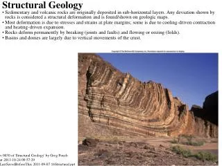
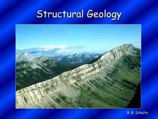
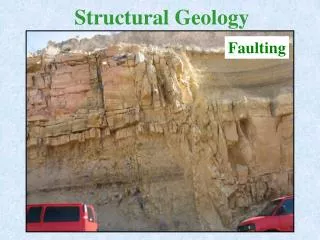
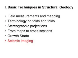
I. Basic Techniques in Structural Geology
I. Basic Techniques in Structural Geology . Field measurements and mapping Terminology on folds and folds Stereographic projections From maps to cross-sections Growth Strata Fault related folds Seismic Imaging. Twiss and Moores, ‘Structural geology’, Chapter 2.

I. Basic Techniques in Structural Geology
E N D
Presentation Transcript
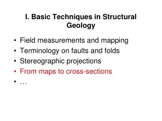
I. Basic Techniques in Structural Geology • Field measurements and mapping • Terminology on folds and folds • Stereographic projections • From maps to cross-sections • Growth Strata • Fault related folds • Seismic Imaging
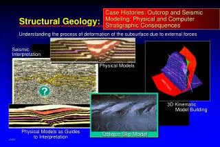
Twiss and Moores, ‘Structural geology’, Chapter 2. • C.M.R. Fowler, ‘The Solid Earth, An introduction to Global Geophysics’ • Shaw, Connors and Suppe, ‘Seismic Interpretation of Contractional Fault-related Folds’ (AAPG Seismic Altlas, #53) • http://principles.ou.edu/seismic_explo/reflect/reflect.html
‘Snell’s laws’ - There is no energy refracted if i>ic, where the critical angle is defined by ic= sin-1(V1/V2) Rock Vp (km/s) Granite 5.0 Basalt 5.5 Limestone 6.0 Sandstone 4.2 Shale 2.5
Seismic Imaging Techniques Source geophones • Seismic reflection • Seismic refraction Direct ic ic time Reflected Refracted
Seismic Imaging Techniques Source geophones • Seismic refraction • Seismic reflection Travel time of P wave V1 ic ic V2 V1 < V2 Critical distance: xc Crossover distance: Xcross
Seismic Imaging Techniques Source geophones • Seismic refraction • Seismic reflection Travel time of P wave V1 V2 V1 < V2 Critical distance: xc Crossover distance: Xcross
Seismic Imaging Techniques Source geophones • Seismic refraction • Seismic reflection Travel time of P wave V1 V2 V1 < V2 Critical distance: xc Crossover distance: Xcross
Seismic Reflection Source geophones Reflection coefficient A typical value for R is 0.001 Reflectors reflect contrasts of acoustic impedance: Polarity of reflected wave depends on sign of reflection coefficient
Simple ‘zero-offset’ Reflection survey • An ‘image’ of the subsurface is obtained by plotting seismograms side by side. • Reflections are generally faint • The ‘image’ obtained this way is in two-way time, not depth. (to convert to depth the velocity needs to be determined). • The cost scales with the number of sources For these reasons it is advantageous to deploy lines of geophones (with a range of ‘offsets’)
Seismic Reflection Source geophones Two-way travel time is: A x C B z Or • t0 is the two-way normal incidence travel time: • An horizontal reflector generates an hyperbola in time • Velocity, V1, and depth,z. can be determined by plotting t2 as function of x2. t0
Seismic Reflection Source geophones Two-way travel time is: A x C B z Or • t0 is the two-way normal incidence travel time: • An horizontal reflector generates an hyperbola in time • Velocity, V1, and depth, z. can be determined by plotting t2 as function of x2. t0
Common Mid- Point (CMP) Stacking The seismograms corresponding to the various offsets can be corrected to account for the effect of the offset on the arrival time (Normal Move Out), and then stacked to simulate a ‘zero offset’ seismograms with enhanced signal to noise ratio. The Normal Move Out is :
Common Mid- Point Stacking • In case of multiple layers the t2-x2 plot yields the ‘Root Mean Square velocity’,VRMS, (also called stacking velocity): • The equation is used to correct for NMO before stacking. • VRMS relates to interval velocity according to Dix’s equation • Interval velocities and thicknesses are determined from
Unmigrated Seismic Reflection Profile • Seismograms are plotted side by side. • Vertical axis is the two-way travel time • A Common Mid-Point (CMP) stacked profile show records as if shots and geophones were coincident
Migration • In a stacked profile all reflections are plotted as if they were coming from vertical ray paths. This is a ‘distorted’ view of the sub-surface. • Diffractions Migration aims at correcting these distortions and diffractions (assuming that all reflections are in the plane of the vertical section along the geophones line).
Distortions Buried focus
Distortions An example with Synthetic seismograms
Most Common ‘Artifacts’ • Multiples (Sediment/Basement interface or water/sea bottom interface in marine survey) • Sideswipes (reflections out of the plane of the section) can mess up the migration process. • Incorrectly migrated diffractions (they look like anticlines but are not) • Pull-up and Pull-down (not really artifacts)
Multiples Source geophones 0 Primary reflection t1 First multiple 2.t1 Time
Reflection seismic Line DLC9708 (Hopper et al., 1997). Extent of corresponding sparker seismic lines marked by thick line at top. Three first multiples can be seen lower in the section
Still not directly an image of the subsurface. Unmigrated Seismic Reflection Profile Migrated Seismic Reflection Profile
Shortcomings in seismic images of folds Folds can be distorted or only partially imaged in seismic sections. Two common shortcomings are: (1) Overlapping reflections in un-migrated or under-migrated sections; (2) lack of imaging of steeply dipping fold limbs. NB: Note alsopullup.