Multi-stage Network
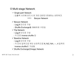
Multi-stage Network. Single-path Network : 입출력 사이에 반드시 한 개의 경로만 존재하는 네트워크 Banyan Network. Banyan Network - Log 2 N 단으로 구성 - Shuffle Exchange 를 재배치한 구조임 Flip Network - Log 2 N 단으로 구성 - 각 단은 inverse shuffle 임 Baseline Network - Log 2 N 단으로 구성

Multi-stage Network
E N D
Presentation Transcript
Multi-stage Network • Single-path Network • : 입출력 사이에 반드시 한 개의 경로만 존재하는 네트워크 • Banyan Network • Banyan Network • - Log2N 단으로 구성 • - Shuffle Exchange를 재배치한 구조임 • Flip Network • - Log2N 단으로 구성 • - 각 단은 inverse shuffle 임 • Baseline Network • - Log2N 단으로 구성 • - 각 단의 입력으로 부터 순차적으로 N, N/2, N/4, ---, 4 입력의 • inverse shuffle로 구성됨 • Shuffle Exchange(Omega) Network
Multi-stage NetworkCont. a. Banyan Network b. Baseline Network c. Suffle Exchange(Omega) d. Flip Network(Inverse Shuffle Exchange)
Delta-2 Network a bit b bit c bit MSB abc c b a abc 000 0 0 0 110 001 1 1 1 010 011 ATM Cell Routing Inform. abc 100 001 101 110 111 1st stage 3rd stage 2nd stage • 스위치 네트워크는 K(N=bK : b=2)단이며, 각 단은 N/b(b=2) 개의 • 단위 스위치로 구성 • 입력에서 출력까지 루팅은 k bit만을 이용함
Multiple-path Network • Internal blocking 감소 혹은 해결 가능 • Internal path는 connection set-up phase에서 결정 • Folded 및 unfolded network으로 구성 • Folded Switch Network • : Internal link는 bidirectional하게 동작 • : Short path (connection 셀이 통과해야 할 switching • element 수는 입출력 link의 위치에 의존함) • : 3-stage folded network에서 port capacity = (k/2)(k/2)k • using k x k switching element
1 k/2 1 k/2 k 1 k/2 k/2 k/2 k/2 k/2 k k/2 1 k/2 Input / Output k/2 k 1 k/2 1 1 k/2 k/2 k/2 k k/2 k/2 k/2 k k/2 • 3-stage folded switching network
Unfolded switching network • Internal link는 unidirectional하게 동작 • 모든 셀은 동일한 switch element 수(단수)만큼 통과해야 함 Input Output Distribution Network Routing Network (a) Basic Structure of a distribution/Banyan network Input Output Routing Network Distribution Network Trap Network • Distribution Network = Sorting Network + Trap Network • Routing Network = Banyan Network (b) Basic Structure of a sorting/trap/Banyan network
Types of Blocking • Internal Blocking • Output Blocking • HOL(Head Of Line) Blocking
2x2 4x4 8x8 bitonic bitonic bitonic sorter sorter sorter 0 0 0 1 1 1 Sorting Network Routing Network (Batcher Network) (Banyan Network) :Up sorter (Large Value goes up) :Down sorter (Large Value goes down) • Batcher-Banyan Switch Network
Performance Model of ATM Switch • Memory Size • : depends on the performance requirement of system • Memory Speed • : depends on the buffering strategy • (size and speed of the internal and output links • Memory Control • : in order to control the queues dependent on the queueing principles
Buffer Strategies of ATM Switch • Input Buffering • Output Buffering • Shared Buffering • Input/Output Buffering
FIFO buffer Output Input Nonblocking Selfrouting Switch Controller FIFO buffer Output Input Arbitor Controller • Input Buffering ATM Switch with Arbitor • 입력측에 FIRO(First In Random Out) 버퍼를 둠 • HOL 특성이 발생하지 않도록 중재회로에서 중재하는 알고리즘 필요 • 한 셀 전송시간은 약 2.7usec이므로, 이 시간 내에 중재 완료
Nonblocking ATM Switch with Feedback Loop
Common Memory Buffer형 ATM Switch 특성 0= variable (0.8 ~ 0.9) i (i = 2 ~8) = 0.8 M=ak : a1 : Completely shared buffer switch a 1/N : Completely separate buffer switch Ref : Noboru ENDO et. al. “ Traffic characteristics evaluation of a shared buffer ATM switch”, Globecom ‘90
Common Memory Buffer형 ATM Switch 특성 • Cell Loss Ratio of Shared Buffer ATM Switch(Imbalanced) • Cell Loss Ratio of CS and SMXQ
Knockout ATM Switch 구조 • Output Buffer Type ATM Switch • Complexity : N2 • Loss Rate : 10-6이하 (L=8 for uniform traffic)
Knockout ATM Switch Concentrator 구조 및 특성 • L=8일 때, 집선기에서 Cell Loss Rate는 1X10⁻⁹임
Knockout ATM Switch Concentrator의 셀 손실 특성 셀은 Uniform 분포이며, 특정 출력에 k개의 셀이 도착할 확률 Pk
1 1 2 Batcher Network Kth Banyan Network N N Statistical multiplexer PART III.ATM Switch Network-2 • Enhanced Sort-Banyan Network Switch • Internal connection resolution mechanism and output port contention • resolution algorithm remain the same • Increase group size k : more than one cells can be simultaneously • received by output port • Increase throughput at the expense of increased complexity
Input Output 1st 1 1 Banyan Network 2 2 kth Banyan N N Network Random router or broadcaster Statistical multiplexer • Parallel Banyan Network • Multiple Banyan Networks in parallel with random or • broadcast routing • Complexity : N log2 N
Input 1 1st Banyan Network 2 kth Banyan Network 2nd Banyan Network N Statistical multiplexer N 1 Output • Tandem Banyan Network • Cascaded Banyan Networks with deflection routing • Complexity : N log2 N Ref : Fouad A. Tobagi,” Architecture, Performance, and Implementation of the Tandem Banyan Fast Packet Switch”,IEEE SAC Vol.9, No.8, Oct., 1991
ATM Switch Size Expansion Single Stage ATM Switch Expansion Single Stage FSM ATM Switch Expansion
Cell Header Processing in Switch Fabrics • In ATM Switching Node • : VPI/VCI translation • : Input Port에서 적절한 출력 Port로 셀 전달 기능 • ---> Selfrouting 및 table-control principle • Selfrouting Switching Elements • : VPI/VCI 변환은 switching network 입력 단에서 수행된 후 • switch network의 internal header(internal routing 정보) • 로 추가됨 • : Cell Header extension 만큼 switch network의 internal • speed 증가
n m Y n Y Header Translation and extension Input Output m n Self- routing switching Element Self- routing switching Element Y X VPI/VCI table VPI/VCI X Y,m,n Switch Network • Selfrouting Switching Elements • k 단 switch network에서 internal header는 k subfield를 가짐 • subfield i 는 i stage switch element의 destination number 임 Header translation at the input : old VPI/VCI ---> new VPI/VCI + internal address
Z Header Translation and extension Header Translation and extension Input Output m n Self- routing switching Element Self- routing switching Element X Y VPI/VCI VPI/VCI table table X Z,m Z Y,n Switch Network Switch Network Header translation at each stage : old VPI/VCI ---> new VPI/VCI + output link • Table-controlled Switching Elements • Cell Header의 VPI/VCI가 translation 됨 • Table 내용은 connection set-up시 update 됨