Download
1 / 34
340 likes | 455 Vues
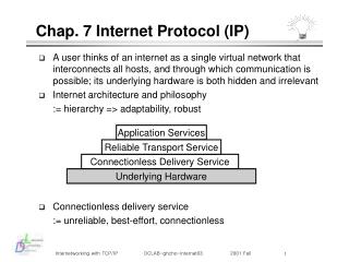
Chap. 7 Internet Protocol (IP). A user thinks of an internet as a single virtual network that interconnects all hosts, and through which communication is possible; its underlying hardware is both hidden and irrelevant Internet architecture and philosophy := hierarchy => adaptability, robust

E N D
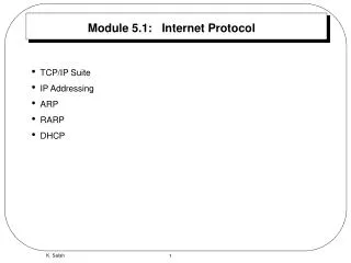
Chap. 7 Internet Protocol (IP) • A user thinks of an internet as a single virtual network that interconnects all hosts, and through which communication is possible; its underlying hardware is both hidden and irrelevant • Internet architecture and philosophy • := hierarchy => adaptability, robust • Connectionless delivery service • := unreliable, best-effort, connectionless Application Services Reliable Transport Service Connectionless Delivery Service Underlying Hardware
IP Network Interface Network Interface Network Interface Hardware Hardware Hardware The Basic of IP (I) Host A Host B Uses TCP/IP Services Application Application TCP TCP Virtual Circuit Gateway G Routes Datagrams IP IP
The Basic of IP (II) • IP provides three important definitions • defines the basic unit of data transfer • performs the routing function • includes a set of rules that embody the idea of unreliable packet delivery, such as packet processing, error control • The unit of hardware transfer is a frame that contains a header and data, where the header gives information, which includes the source and destination addresses • The unit of Internet transfer is a datagram, which has the same structure as the frame • Because datagram processing occurs in software, the contents and format are not constrained by any hardware
IP Format (I) • Format of an Internet datagram 0 15 31 Vers Service Type Total Length HLen IP Identification Flags Fragment Offset Time to Live Header Checksum Protocol Num. Source IP Address Destination IP Address Options Padd. Data (variable length)
IP Format (II) • Vers : IP version number, currently 4 • HLen : IP header length in word (16) • Total Length : IP datagram length in octets (65535) • Service type field : a kind of transport specification • this is only a hint to the routing algorithm, that is, it does not guarantee the type of transport requested • Data encapsulation : to support the different physical frame 0 1 2 3 4 5 6 7 Precdence D T R unused Dataram Header Datagram data area Frame Header Frame Data Area
IP Format (III) • Now, the problem is the difference size between IP datagram (40 ~ 65535) and physical frame • The network’s maximum transfer unit (MTU) • - Ethernet : 1500, FDDI : 4470, someone : 128, ATM : 54 … • Total Length : IP datagram length in octets (65535) • Again, Internet design basement is to hide underlying network technologies and make communication convenient for the user • A datagram does not always fit into a single network frame • How the Internet has resolved this problem? • permit to use any size of datagram, and arranges a way to divide large datagrams into smaller pieces when the datagram needs to traverse a network that has a small MTU • This process of dividing a datagram is called as fragmentation, and the small pieces into which a datagram is divided are called as fragment
IP Format (IV) • Fragmentation example (pp. 96, 97) H2 H1 Net 3 Net 1 R2 R1 MTU = 1500 MTU = 1500 Net 2 MTU = 620 Data1 600 octets Data2 600 octets Data3 300 octets Dataram Header Fragment1 Header Data1 Fragment 1 (offset 0) Fragment1 Header Data2 Fragment 2 (offset 600) Fragment1 Header Data3 Fragment 3 (offset 1200)
IP Format (V) • Identification : a unique integer that identifies the datagram, the destination uses it along with the datagram source address to identify the datagram • Flag : - + do not fragment + more fragment • Fragment Offset : the offset in the original datagram of the data being carried in the fragment, in units of 8 octets • TTL : how long, in seconds, the datagram is allowed to remain in the Internet, but usually handled with the number of hop • Protocol : which high-level protocol was used to create the message being carried in the DATA area of a datagram • Header Checksum : checksum the header as a sequence of 16 bit integers, adding them using 1’s complement arithmetic • Source and Destination Addresses • IP Option • Padding : 32 bit alignment
Datagram Option (I) • Aims for network testing or debugging • The length varies depending on which options are selected • Option format • Copy : how routers treat options during fragmentation • Option number : network control + - + debugging + - 0 8 16 Option code Length Option data (variable) 0 1 3 7 Copy Option class Option number
Datagram Option (II) Refer to pp. 102 Option Class Option Number Description Length 0 0 - End of option list. Used if options do not end at end of header 0 1 - No operation (used to align octets in a list of operations) 0 2 11 Security and handling restrictions (for military applications) 0 3 var Loose source routing. Used to route a datagram along a specified path 0 7 var Record route. Used to trace a route 0 8 4 Stream identifier. Used to carry a SATNET stream identifier (Obsolete) 0 9 var Strict source routing. Used to route a datagram along a specified path 2 4 var Internet timestamp. Used to record timestamps along the route
Datagram Option (III) • Record route option : provide a way to monitor or control how internet routers route datagrams • create an empty list of IP addresses • arrange for each router that handle the datagram to add its IP address to the list 0 8 16 24 31 Code (7) Length Pointer Not used First IP address Second IP address ...
Chap. 8 Routing IP Datagrams (I) • In a packet switching network, routing refers to the process of choosing a path over which to send datagrams • In the Internet, the IP layer chooses the next hop for each datagram that it sends • single homed host vs. multi-homed host subnet 2 subnet 3 subnet 4 R1 R2 subnet 1 Host
Direct delivery vs. Indirect delivery • Direct delivery : if the datagrams is destined for a host that is on a directly connected network, it is sent directly to the host • does not involve routers • identify the destination using the ARP (mapping from IP address to a corresponding physical address) • encapsulates the datagram in a physical frame (if necessary, the datagram may fragmented) in order to passing down • how can it find out the destination lies on a directly connected? • Indirect delivery : for destinations that are not on a directly connected network, the IP layer must decide to which next-hop gateway to send the datagram, based on the network ID portion of the destination IP address • how can a router know where to send each datagram?
Table-driven IP Routing(I) • The IP routing algorithm employs an Internet routing table on each machine (host and router), which contains information about the possible destinations and how to reach them • It consults the table to decide where to send the datagram • Then what information should be kept in routing tables? • minimal information principle : keep network prefix only • - makes routing efficient and keeps routing table small • information hiding principle : the details of specific hosts confined to the local environment : next- hop routing • - the routing table in a router only specifies one step along the path from the router to a destination • default routing : if no route appears in the table, the routing routines send the datagram to a default router - it makes their routing decisions efficiently to possible distant destinations
Table-driven IP Routing (Example) • Refer to pp 114 20.0.0.5 30.0.0.6 40.0.0.7 Network 10.0.0.0 Network 20.0.0.0 Network 30.0.0.0 Network 40.0.0.0 Q R S 10.0.0.5 20.0.0.6 30.0.0.7 To reach hosts on network Route to this address 20.0.0.0 Deliver Directly 30.0.0.0 Deliver Directly 10.0.0.0 20.0.0.5 40.0.0.0 30.0.0.7
Routing Algorithm Refer to pp. 116 Route_IP_Datagram(datagram, routing_table) Extract destination IP address, ID, from datagram Compute IP address of destination network, IN if IN matches any directly connected network address send datagram to destination over that network; else if ID appears as a host-specific route route datagram as specified in the table; else if IN appears in routing table route datagram as specified in the table; else if a default route has been specified route datagram to the default gateway; else declare a routing error;
IP Routing (I) • IP routing is based on the destination network ID alone, what? • all IP traffic for a given network tales the same path regardless to the delay or throughput of physical network • only the final router can determine if the destination exists or is operational, the router only can report the delivery to the sender • each router routes traffic independently - someone should find out if two-way communication is always possible • IP routing selects the next hop to be sent the datagram, what? • where does IP store the next hop address? not IP itself! • IP simply passes the datagram and the next hop address to the network interface software (so-called network driver) • the driver software responsible for the physical network over which the datagram must be sent - binds the next hop IP address to a physical address, forms a frame, and sends it
IP Routing (II) • Routing tables store the IP address of a next hop for each destination network • When those addresses must be translated into corresponding physical addresses before the datagram can be sent? initialize Data stream to be sent Routing Table IP address reference Routing Algorithm Datagram to be sent update Network Driver physical address Datagram to be sent + physical address Network Board
IP Routing (III) • Why does IP S/W avoid using physical addresses when storing and computing routes? • provides a clean interface between IP and high-level • provides an easy method to maintain the routing table • provides an abstraction hides the details of underlying networks • When a host (a router) received a datagram • if the datagram’s destination address matches the host’s IP address, IP accepts the datagram and passes it to high-level • else, simply discard the datagram (in the case of a host) • else, forward the datagram using the standard routing • algorithm (in the case of a router) • why a host should not route datagrams? • 1. bad effect propagation 2. unnecessary network traffic • 3. simple errors can cause chaos • 4. a host does not has any function to correct the route
Broadcast and Multicast • Broadcast: no filtering done at net interface • limited: to local net => 255.255.255.255 • net: to all on specified net => netid.x, where x is the all ones host portion of the address • subnet: to all on specified subnet => netid.subnetid.x • all subnets: to all on subnets of one net => the host portion of the address is all ones • Multicasting: like broadcasting, but: • multicast messages are sent to multicast group addresses • individual interfaces can select group addresses of interest • Distribution handled by collection of multicast routers • IGMP (internet group management protocol) used to manage group membership • DVMRP, PIM ...
Chap. 9 ICMP (Internet Control Message Protocol) (I) • ICMP allows routers to send error or control message to other routers or hosts; it provides communication between the IP software on one machine and on another • Usually used to provide information about problems : Not intended to make IP reliable, but to improve the operation of the internet • failures of communication lines and processors • a temporarily or permanently disconnection from the network • the time-to-live counter expiration • network congestion • ICMP messages are grouped into two classes • error message : destination unreachable, source quench, redirect, time exceeded, parameter problem • query message : echo request/ reply, timestamp request/reply, information request/reply, address mask request/reply
ICMP (II) • ICMP is built on top of IP, but is considered an integral part of IP • ICMP message are transmitted as the data portion of an IP datagram • ICMP header ICMP header IP header Optional data ICMP message IP datagram 0 8 16 24 31 type code checksum identifier sequence number optional data
ICMP Examples : ping • Use ICMP echo request/reply • Source can calculate round trip time (RTT) of packets
ICMP Examples : traceroute • Records the route that packets take • To determine the route, progressively increase TTL
The Internet Routing Architecture (I) • Internet = a core system + a set of autonomous systems • The core system is the glue, as which • is controlled by the INOC(Internet Network Operations Center) • provides reliable and consistent routers for all possible dest. • does not use the default route • has complete infor. about optimal routes to all possible dest. • The autonomous system is an ever-growing component of core system, as which • is a collection of networks and gateways managed by one administrative authority • are hierarchically grouped into an autonomous system (nesting) • allows gateways to advertise only the reachability of those networks within the gateway’s autonomous system • restricts the Internet’s topology to a tree structure in which a core system forms the root - only one path from the core system
Gateway 1 Gateway 2 Gateway 3 Autonomous System 1 Autonomous System 2 Autonomous System 3 The Internet Routing Architecture (II) • Core system : GGP (Gateway-to-Gateway Protocol) • Core and autonomous system(s) : EGP (Exterior Gateway Protocol) • Autonomous system : IGP (Interior Gateway Protocol) Core System