Exotic Bunch spacing for scrubbing
140 likes | 246 Vues
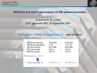
Explore the considerations of accommodating non-standard bunch spacings in RF systems and adapting beam control mechanisms for optimal performance. Learn about key strategies for maintaining efficiency without extensive system upgrades.

Exotic Bunch spacing for scrubbing
E N D
Presentation Transcript
LBOC Exotic Bunch spacing for scrubbing RF considerations P. Baudrenghien, J. Esteban Mueller, D. Valuch BE-RF
LBOC Sure we can deal with any bunch spacing multiple of 2.5 ns • The LHC RF is a single-frequency system at 400 MHz and can therefore deal with bunches spaced by multiples of 2.5 ns • However the subsequent questions are • Can this be done without major upgrade to the LLRF system that “assumed” a 25 ns bunch spacing? Subject of this talk. • Can the SPS and/or the SPS-LHC transfer be adapted so that “exotic” beams are captured with reasonable losses? Subject of Juan’s talk, next LBOC
LBOC The LHC RF system (IP4)
LBOC The fast local loop in UX45 is clocked at 40 MSPS but it does not use beam signal. It will work with any bunch pattern.
LBOC The beam control in SR4 uses PU signal and will be affected by the bunch pattern.
LBOC Beam Control • The LHC Beam Phase Loop: • With 25 ns spaced bunches, we measure the phase of each bunch individually • Then we average over the desired pattern using a mask • The result updates the RF frequency at every turn
LBOC SPS beam phase loop • Beam phase = phase of the RF component of beam current • Single bunch response: The 200 MHz BPF has a short impulse response (250 ns FWHM). It effectively averages over 10 bunches (25 ns spacing)
LBOC SPS (cont’d) • Batch response: The phase measurement is an average over the last ~ 10 bunches before the sampling In the SPS, the averaging over bunches is done in the RF domain, before extraction of the phase information
LBOC LHC bunch phase loop • Bunch phase = phase of each bunch, if 25 ns spacing (or multiple) • Beam phase = average over the individual phases, using a dynamic bunch mask The IQ Demodulator gives the coordinates of the wavelet, in a system with the RF on the x-axis The ADCs are clocked ~ 20 ns after the passage of the bunch. They give clean (I,Q) coordinates of the corresponding wavelet, from which the phase is extracted The 400 MHz BPF has a short impulse response (20 ns FW), so that bunches spaced at 25 ns do not couple The LPF reduces the noise added by the demodulation. Their step response is 10-20 ns In the LHC, the averaging is done on the phase measurements
LBOC 5 + 20 ns spacing The measurement correctly averages over the two bunches if the risetime of the LPF is below 15 ns. Below, the BPF output caused by bunch1 alone (assumed 0 degree phase @ 400 MHz) and bunch2 alone (assumed 90 degrees phase shift @ 400 MHz) Sample here Two bunches, 5 ns spacing Atop, the BPF output sum (blue) and the equivalent with a single bunch at 45 degrees phase shift (red). The averaging is first done on the RF signal for bunch pairs, then on the individualphase measurements
LBOC 2.5 + 22.5 ns spacing The measurement correctly averages over the two bunches if the risetime of the LPF is below 17.5 ns. Bunch1 (assumed 0 degree phase @ 400 MHz) is followed by bunch2 (assumed 90 degrees phase shift @ 400 MHz) after 2.5 ns Sample here! Two bunches, 5 ns spacing The use of a 400 MHz BPF gives a usable wavelet for any bunch spacing compatible with the RF buckets Atop, the BPF output sum (blue) and the equivalent with a single bunch at 45 degrees phase shift (red).
LBOC Conclusions (1) • With 2.5+22.5 or 5+20 bunch spacing the existing phase measurements (every 25 ns) will average over the bunch pairs • To perform best, the LPF BW must be increased. This can be prepared in the lab in 2014 • A small “leaking” in the next 25 ns measurement must be expected as the BPF impulse response is not strictly zero after 20 ns • The phase loop can be ON at injection with 5+20 ns scheme. It must be OFF with 2.5+22.5 (bunch splitting at LHC injection) for the incoming batch, but ON for the circulating batches. This “dynamic masking” was tested during MD in 2013 (Batch by batch blow-up at injection)
LBOC Conclusions (2) • Capture losses are an issue with both schemes. The capture voltage can be increased (12 MV) • With 5+20 ns spacing, the bunch length must stay below 1.8 ns (4 sigma). If that is possible capture losses will not be larger than with standard 25 ns spacing • The 2.5+22.5 ns scenario calls for non-adiabatic splitting in the LHC (injection on the 0 degree stable phase) and capture losses cannot be avoided. RF gymnastics are proposed to limit these losses. See Juan’s talk at the next meeting
LBOC Thank you for your attention