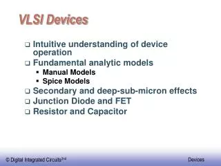
2. VLSI Basic
2. VLSI Basic. Hiroaki Kunieda Dept. of Communication and Integrated Systems Tokyo Institute of Technology. VLSI Design with Verification. Specification. System Design. System Verification. RTL. Logic Design. Logic Verification. Netlist. Layout Design. Layout Verification. Mask Data


2. VLSI Basic
E N D
Presentation Transcript
2. VLSI Basic Hiroaki Kunieda Dept. of Communication and Integrated Systems Tokyo Institute of Technology
VLSI Design with Verification Specification System Design System Verification RTL Logic Design Logic Verification Netlist Layout Design Layout Verification Mask Data Test Data
Logic Theory [Completeness] • Function {|}=NAND function: complete • 1: a|(a|a) = a|a’ = 1 • 0: {a|(a|a}|{a|(a|a)} = 1|1 = 0. • a’: a|a = a’. • ab: (a|b)|(a|b) = ab • a+b: (a|a)|(b|b) = a’|b’=a+b • NOR function: complete • AND and OR function: not complete [Irredundant] no literal can be removed. redundant Ab+ab’=a
MOS • “MOS” : sandwichstructure of Metal, Oxide, and Silicon (semiconductor substrate). • The positive voltage on the polysilicon forms gate attracts the electron at the top of the channel. • The threshold voltage (Vt) collects enough electrons at the channel boundary to form an inversion layer (p -> n). Field Oxide Gate Oxide
Transistor Parasitics • Cg: gate capacitance = 0.9fF/μm2 (2 μprocess) • Cgs/Cgd: source/drain overlap capacitance =Cox W (Cox: gate/bulk overlap capacitance)
A Simple Transistor Model Linear region Saturated region • nMOS transistor become on by applying high voltage to gate to provide current. • pMOS transistor becomes on by applying low voltage to gate to provide current
Static Complementary Gates VDD Pullup network (pMOS) • output is connected to VDD Ro/W CoW Ro/W CoW Pulldown network (nMOS) • Output is connected to VSS Pull down Pull up VSS
Vin-Vout DC Characteristics VOH Noise Margin NML = VIL-VOL NMH = VOH-VIH VIH VOL VIL
CMOS NAND & NOR Pullup network (pMOS) • output is connected to VDD when ab=0. VDD Pulldown network (nMOS) • Output is connected to VSS when ab=1. VSS
Relation between nMOS and pMOS Dual graph
And Or Inverter (AOI) gate (ab+c)’
Adders si =aibici =(aibi)ci = Pici ci+1=aici+bici+aibi=(aibi)ci+aibi =Pici+Gi
1.3 Gate Delay and Wire Delay
Gate Delay (delay model) Let’s suppose that Wp = 2 Wn which makes the same pull up and pull down current with ON-resistance of, Ro/W where Ro is the resistance per unit width. (ex. 200Ωum) Load capacitance consisting of drain junction capacitance is corresponded by the area of the drain such as CoW where Co is the capacitance per unit width (ex. 50 fF/um) Input capacitance is also represented by CoW L=35 nm=0.035 um (45nm)
Gate Delay CoW Ro/W Ro/W CoW Pull down Pull up Pull up current is represented by VDD/Ron(p). Pull down current is represented by VDD/Ron(n) Gate Delay (W=0.35um, L=0.035um) = (Ro/W) x (CoW) = Ro Co = 200 Ωum x 50pF/um =10psec Pull up/downcurrents are represented by ON resistance, which are reversely corresponded by the channel width W.
2 stage gates without load • The first term represents the delay of the 1st stage, where the output charge and the input charge of the 2nd stage is pull up or down by the current driven by the 1st gate. Both charge and current corresponds to the size or the channel width w. • The second term represents the delay of the 2nd stage. Without any load to the gates, the delay becomes identical to, which depends on the process. Delay = 1st stage delay + 2nd stage delay = (Ro/W1) (CoW1+CoW2) + (Ro/W2)(CoW2) = RoCo (2+W2/W1) = 10 psec x 3 = 30 psec
2 stage gates with load Load Capacitance is total sum of input capacitance CoWload Delay = 1st stage delay + 2nd stage delay = (Ro/W1) (CoW1+CoW2) + (Ro/W2)(CoW2+CoWload) = RoCo (2+W2/W1+Wload/W2) Case 1. W2=W1, Load=10W1 Delay = 10 psec (2+1+10) = 130.0 psec Case 2. W2=3W1, Load=10W1 Delay = 10 psec (2+3+3.33) =83.3 psec
Wires DelayElmore Delay Model Delta1=r1 x (C1+---+Cn) =n tc Delta2=r2 x (C2+----+Cn) =(n-1)tc DeltaN=rn x Cn =tc total=Delta1+ ----- + DeltaN =[n(n+1)/2] tc
Wire Delay Rline=2.0 Ω-um Cline=0.3fF/um Ro=200 Ω*um Co= 50 fF/um W1=W2=0.35u Line=2N um Delay=(R0/W1) (CoW1+CoW2+ClineLine) +(RlineLine) (CoW2+(Cline/2)Line) =200 x (2x50f + 2xN)+2 x (10f+0.5N) = 50 nsec + 26*N nsec (line =2xN um) Delay = Ro/W1 (CoW1+CoW2) =2.5K x 20fF =50.0 nsec (line=0)
Wire Delay Rline=500 Ω/um Cline=300 fF/um Ro=25 kΩ*um Co=0.5 fF/um W1=W2=0.35u Line=0.5um Delay=(R0/W1) (CoW1+CoW2+ClineLine) +(Ro/W1+RlineLine) (CoW2+(Cline/2)Line) =50K x (0.5 f + 50K x (0.25+0.125) = 37.5 nsec + 18.8 nsec =56.3 nsec (line =0.5 um) Delay = Ro/W1 (CoW1+CoW2) =50K x 0.5fF =25 nsec (line=0)
Switch Logic Logic 0 transfer Logic 1 transfer
Latch Charge sharing: the stored data of A is connected to the latch’s output. Additional buffer may be required to drive output load.
Clocked Inverter • tristate inverter produces restored output or Hi-Impedance Z • Used as latch circuit
Scan in DFF Functional Schematic of DFF with Scan ACSEL Lab University of California, Davis
Memory Structure Read-Only Memory (ROM) Random Access Memory (RAM) Static RAM (SRAM) Dynamic RAM (DRAM)
Static RAMCell • Read • Precharge bit and bit’ • Asert Select line • Write • Bit and bit’ lines are set to desired values. • Select is set to 1.
RAM Cell • Write • set bit line • Read • Precharge firstly bit line • Activate word line
1.5 Data Path and Control Circuit
Data Path 2 During Clk=2, adder operation must be completed within 1 clock.