Download
1 / 60
600 likes | 699 Vues
Explore the concepts of pipelining in ISAs, its benefits, and challenges associated with implementation and performance. Learn about traditional issues, lessons, and techniques used in modern pipelines like SPARC, MIPS, and x86 architectures.

E N D
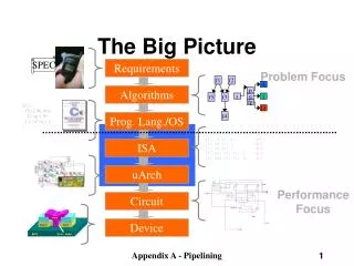
f1 f2 f5 f3 f4 i p s q j fp f3 The Big Picture SPEC Requirements Problem Focus Algorithms f2() { f3(s2, &j, &i); *s2->p = 10; i = *s2->q + i; } Prog. Lang./OS i1: ld r1, b <p1> i2: ld r2, c <p1> i3: ld r5, z <p3> i4: mul r6, r5, 3 <p3> i5: add r3, r1, r2 <p1> ISA uArch Performance Focus Circuit Device Appendix A - Pipelining
Instruction Set Architecture Application …SPARC MIPS ARM x86 HP-PA IA-64… Instruction Set Architecture Intel Pentium X AMD K6, Athlon, Opteron Transmeta Crusoe TM5x00 Implementation Appendix A - Pipelining
Instruction Set Architecture • Strong influence on cost/performance • New ISAs are rare, but versions are not • 16-bit, 32-bit and 64-bit X86 versions • Longevity is a strong function of marketing prowess Appendix A - Pipelining
Traditional Issues • Strongly constrained by the number of bits available to instruction encoding • Opcodes/operands • Registers/memory • Addressing modes • Orthogonality • 0, 1, 2, 3 address machines • Instruction formats • Decoding uniformity Appendix A - Pipelining
Introduction A.1 What is Pipelining? A.2 The Major Hurdle of Pipelining-Structural Hazards • Data Hazards • Control Hazards A.3 How is Pipelining Implemented A.4 What Makes Pipelining Hard to Implement? A.5 Extending the MIPS Pipeline to Handle Multi-cycle Operations Appendix A - Pipelining
A B C D What Is Pipelining • Laundry Example • Ann, Brian, Cathy, Dave each have one load of clothes to wash, dry, and fold • Washer takes 30 minutes • Dryer takes 40 minutes • “Folder” takes 20 minutes Appendix A - Pipelining
A B C D What Is Pipelining 6 PM Midnight 7 8 9 11 10 Time Sequential laundry takes 6 hours for 4 loads If they learned pipelining, how long would laundry take? 30 40 20 30 40 20 30 40 20 30 40 20 T a s k O r d e r Appendix A - Pipelining
30 40 40 40 40 20 A B C D What Is PipeliningStart work ASAP 6 PM Midnight 7 8 9 11 10 • Pipelined laundry takes 3.5 hours for 4 loads Time T a s k O r d e r Appendix A - Pipelining
30 40 40 40 40 20 A B C D What Is Pipelining Pipelining Lessons 6 PM 7 8 9 • Pipelining doesn’t help latency of single task, it helps throughput of entire workload • Pipeline rate limited by slowest pipeline stage • Multiple tasks operating simultaneously • Potential speedup = Numberpipe stages • Unbalanced lengths of pipe stages reduces speedup • Time to “fill” pipeline and time to “drain” it reduces speedup Time T a s k O r d e r Appendix A - Pipelining
What Is Pipelining MIPS Without Pipelining Instruction Fetch Instr. Decode Reg. Fetch Execute Addr. Calc Memory Access Write Back IR L M D Appendix A - Pipelining
What Is Pipelining Instruction Fetch Instr. Decode Reg. Fetch Execute Addr. Calc Memory Access Write Back IR L M D MIPS Functions Passed To Next Stage IR <- Mem[PC] NPC <- PC + 4 Instruction Fetch (IF): Send out the PC and fetch the instruction from memory into the instruction register (IR); increment the PC by 4 to address the next sequential instruction. IR holds the instruction that will be used in the next stage. NPC holds the value of the next PC. Appendix A - Pipelining
What Is Pipelining Instruction Fetch Instr. Decode Reg. Fetch Execute Addr. Calc Memory Access Write Back IR L M D MIPS Functions Passed To Next Stage A <- Regs[IR6..IR10]; B <- Regs[IR10..IR15]; Imm <- ((IR16) ##IR16-31 Instruction Decode/Register Fetch Cycle (ID): Decode the instruction and access the register file to read the registers. The outputs of the general purpose registers are read into two temporary registers (A & B) for use in later clock cycles. We extend the sign of the lower 16 bits of the Instruction Register. Appendix A - Pipelining
What Is Pipelining Instruction Fetch Instr. Decode Reg. Fetch Execute Addr. Calc Memory Access Write Back IR L M D MIPS Functions Passed To Next Stage A <- A func. B cond = 0; Execute Address Calculation (EX): We perform an operation (for an ALU) or an address calculation (if it’s a load or a Branch). If an ALU, actually do the operation. If an address calculation, figure out how to obtain the address and stash away the location of that address for the next cycle. Appendix A - Pipelining
What Is Pipelining Instruction Fetch Instr. Decode Reg. Fetch Execute Addr. Calc Memory Access Write Back IR L M D MIPS Functions Passed To Next Stage A = Mem[prev. B] or Mem[prev. B] = A MEMORY ACCESS (MEM): If this is an ALU, do nothing. If a load or store, then access memory. Appendix A - Pipelining
What Is Pipelining Instruction Fetch Instr. Decode Reg. Fetch Execute Addr. Calc Memory Access Write Back IR L M D MIPS Functions Passed To Next Stage Regs <- A, B; WRITE BACK (WB): Update the registers from either the ALU or from the data loaded. Appendix A - Pipelining
The Basic Pipeline For MIPS Latches between each stage provide pipelining. Appendix A - Pipelining
Reg Reg Reg Reg Reg Reg Reg Reg Ifetch Ifetch Ifetch Ifetch DMem DMem DMem DMem ALU ALU ALU ALU Cycle 1 Cycle 2 Cycle 3 Cycle 4 Cycle 5 Cycle 6 Cycle 7 The Basic Pipeline For MIPS I n s t r. O r d e r Figure 3.3 Appendix A - Pipelining
Pipeline Hurdles • A.1 What is Pipelining? • A.2 The Major Hurdle of Pipelining-Structural Hazards • -- Structural Hazards • Data Hazards • Control Hazards • A.3 How is Pipelining Implemented • A.4 What Makes Pipelining Hard to Implement? • A.5 Extending the MIPS Pipeline to Handle Multi-cycle Operations Limits to pipelining:Hazards prevent next instruction from executing during its designated clock cycle • Structural hazards: HW cannot support this combination of instructions (single person to fold and put clothes away) • Data hazards: Instruction depends on result of prior instruction still in the pipeline (missing sock) • Control hazards: Pipelining of branches & other instructions that change the PC • Common solution is to stall the pipeline until the hazard is resolved, inserting one or more “bubbles” in the pipeline Appendix A - Pipelining
Pipeline Hurdles Definition • conditions that lead to incorrect behavior if not fixed • Structural hazard • two different instructions use same h/w in same cycle • Data hazard • two different instructions use same storage • must appear as if the instructions execute in correct order • Control hazard • one instruction affects which instruction is next Resolution • Pipeline interlock logic detects hazards and fixes them • simple solution: stall • increases CPI, decreases performance • better solution: partial stall • some instruction stall, others proceed better to stall early than late Appendix A - Pipelining
Reg Reg Reg Reg Reg Reg Reg Reg Reg Reg Ifetch Ifetch Ifetch Ifetch DMem DMem DMem DMem ALU ALU ALU ALU ALU Time (clock cycles) Cycle 1 Cycle 2 Cycle 3 Cycle 4 Cycle 5 Cycle 6 Cycle 7 I n s t r. O r d e r Load DMem Instr 1 Instr 2 Instr 3 Ifetch Instr 4 Structural Hazards When two or more different instructions want to use same hardware resource in same cycle e.g., MEM uses the same memory port as IF as shown in this slide. Figure 3.6 Appendix A - Pipelining
Reg Reg Reg Reg Reg Reg Reg Reg Ifetch Ifetch Ifetch Ifetch DMem DMem DMem ALU ALU ALU ALU Time (clock cycles) Cycle 1 Cycle 2 Cycle 3 Cycle 4 Cycle 5 Cycle 6 Cycle 7 I n s t r. O r d e r Load DMem Instr 1 Instr 2 Bubble Bubble Bubble Bubble Bubble Stall Instr 3 Structural Hazards This is another way of looking at the effect of a stall. Figure 3.7 Appendix A - Pipelining
Structural Hazards This is another way to represent the stall we saw on the last few pages. Appendix A - Pipelining
Structural Hazards Dealing with Structural Hazards Stall • low cost, simple • Increases CPI • use for rare case since stalling has performance effect Pipeline hardware resource • useful for multi-cycle resources • good performance • sometimes complex e.g., RAM Replicate resource • good performance • increases cost (+ maybe interconnect delay) • useful for cheap or divisible resources Appendix A - Pipelining
Structural Hazards Structural hazards are reduced with these rules: • Each instruction uses a resource at most once • Always use the resource in the same pipeline stage • Use the resource for one cycle only Many RISC ISA’a designed with this in mind Sometimes very complex to do this. For example, memory of necessity is used in the IF and MEM stages. Some common Structural Hazards: • Memory - we’ve already mentioned this one. • Floating point - Since many floating point instructions require many cycles, it’s easy for them to interfere with each other. • Starting up more of one type of instruction than there are resources. For instance, the PA-8600 can support two ALU + two load/store instructions per cycle - that’s how much hardware it has available. Appendix A - Pipelining
Structural Hazards This is the example on Page 144. We want to compare the performance of two machines. Which machine is faster? • Machine A: Dual ported memory - so there are no memory stalls • Machine B: Single ported memory, but its pipelined implementation has a 1.05 times faster clock rate Assume: • Ideal CPI = 1 for both • Loads are 40% of instructions executed SpeedUpA = Pipeline Depth/(1 + 0) x (clockunpipe/clockpipe) = Pipeline Depth SpeedUpB = Pipeline Depth/(1 + 0.4 x 1) x (clockunpipe/(clockunpipe / 1.05) = (Pipeline Depth/1.4) x 1.05 = 0.75 x Pipeline Depth SpeedUpA / SpeedUpB = Pipeline Depth / (0.75 x Pipeline Depth) = 1.33 • Machine A is 1.33 times faster Appendix A - Pipelining
Data Hazards • A.1 What is Pipelining? • A.2 The Major Hurdle of Pipelining-Structural Hazards • -- Structural Hazards • Data Hazards • Control Hazards • A.3 How is Pipelining Implemented • A.4 What Makes Pipelining Hard to Implement? • A.5 Extending the MIPS Pipeline to Handle Multi-cycle Operations These occur when at any time, there are instructions active that need to access the same data (memory or register) locations. Where there’s real trouble is when we have: instruction A instruction B and B manipulates (reads or writes) data before A does. This violates the order of the instructions, since the architecture implies that A completes entirely before B is executed. Appendix A - Pipelining
Data Hazards Execution Order is: InstrI InstrJ I: add r1,r2,r3 J: sub r4,r1,r3 Read After Write (RAW) InstrJ tries to read operand before InstrI writes it • Caused by a “Dependence” (in compiler nomenclature). This hazard results from an actual need for communication. Appendix A - Pipelining
I: sub r4,r1,r3 J: add r1,r2,r3 K: mul r6,r1,r7 Data Hazards Execution Order is: InstrI InstrJ Write After Read (WAR)InstrJ tries to write operand before InstrI reads i • Gets wrong operand • Called an “anti-dependence” by compiler writers.This results from reuse of the name “r1”. • Can’t happen in MIPS 5 stage pipeline because: • All instructions take 5 stages, and • Reads are always in stage 2, and • Writes are always in stage 5 Appendix A - Pipelining
I: sub r1,r4,r3 J: add r1,r2,r3 K: mul r6,r1,r7 Data Hazards Execution Order is: InstrI InstrJ Write After Write (WAW) InstrJ tries to write operand before InstrI writes it • Leaves wrong result ( InstrI not InstrJ ) • Called an “output dependence” by compiler writersThis also results from the reuse of name “r1”. • Can’t happen in MIPS 5 stage pipeline because: • All instructions take 5 stages, and • Writes are always in stage 5 • Will see WAR and WAW in later more complicated pipes Appendix A - Pipelining
Data Hazards • Simple Solution to RAW • Hardware detects RAW and stalls • Assumes register written then read each cycle • + low cost to implement, simple • -- reduces IPC • Try to minimize stalls • Minimizing RAW stalls • Bypass/forward/shortcircuit (We will use the word “forward”) • Use data before it is in the register • + reduces/avoids stalls • -- complex • Crucial for common RAW hazards Appendix A - Pipelining
Reg Reg Reg Reg Reg Reg Reg Reg Reg Reg Ifetch Ifetch Ifetch DMem DMem DMem Ifetch Ifetch DMem DMem ALU ALU ALU ALU ALU Time (clock cycles) EX WB MEM IF ID/RF I n s t r. O r d e r add r1,r2,r3 sub r4,r1,r3 and r6,r1,r7 or r8,r1,r9 xor r10,r1,r11 Data Hazards The use of the result of the ADD instruction in the next three instructions causes a hazard, since the register is not written until after those instructions read it. Figure 3.9 Appendix A - Pipelining
Reg Reg Reg Reg Reg Reg Reg Reg Reg Reg ALU ALU ALU Ifetch ALU DMem ALU Ifetch Ifetch DMem DMem Ifetch Ifetch DMem DMem Time (clock cycles) I n s t r. O r d e r add r1,r2,r3 sub r4,r1,r3 and r6,r1,r7 or r8,r1,r9 xor r10,r1,r11 Forwarding is the concept of making data available to the input of the ALU for subsequent instructions, even though the generating instruction hasn’t gotten to WB in order to write the memory or registers. Data Hazards Forwarding To Avoid Data Hazard Figure 3.10 Appendix A - Pipelining
Reg Reg Reg Reg Reg Reg Reg Reg ALU Ifetch Ifetch Ifetch Ifetch DMem DMem DMem DMem ALU ALU ALU Time (clock cycles) lwr1, 0(r2) I n s t r. O r d e r sub r4,r1,r6 and r6,r1,r7 or r8,r1,r9 The data isn’t loaded until after the MEM stage. Data Hazards There are some instances where hazards occur, even with forwarding. Figure 3.12 Appendix A - Pipelining
Reg Reg Reg Ifetch Ifetch Ifetch Ifetch DMem ALU Time (clock cycles) I n s t r. O r d e r lwr1, 0(r2) Bubble sub r4,r1,r6 ALU ALU Reg Reg DMem DMem Bubble and r6,r1,r7 Reg Reg Bubble ALU DMem or r8,r1,r9 The stall is necessary as shown here. Data Hazards There are some instances where hazards occur, even with forwarding. Figure 3.13 Appendix A - Pipelining
This is another representation of the stall. Data Hazards Appendix A - Pipelining
Pipeline Scheduling Data Hazards • Instruction scheduled by compiler - move instruction in order to reduce stall. • lw Rb, b code sequence for a = b+c before scheduling • lw Rc, c • Add Ra, Rb, Rc stall • sw a, Ra • lw Re, e code sequence for d = e+f before scheduling • lw Rf, f • sub Rd, Re, Rf stall • sw d, Rd • Arrangement of code after scheduling. • lw Rb, b • lw Rc, c • lw Re, e • Add Ra, Rb, Rc • lw Rf, f • sw a, Ra • sub Rd, Re, Rf • sw d, Rd Appendix A - Pipelining
Pipeline Scheduling Data Hazards Appendix A - Pipelining
Control Hazards • A.1 What is Pipelining? • A.2 The Major Hurdle of Pipelining-Structural Hazards • -- Structural Hazards • Data Hazards • Control Hazards • A.3 How is Pipelining Implemented • A.4 What Makes Pipelining Hard to Implement? • A.5 Extending the MIPS Pipeline to Handle Multi-cycle Operations A control hazard is when we need to find the destination of a branch, and can’t fetch any new instructions until we know that destination. Appendix A - Pipelining
Reg Reg Reg Reg Reg Reg Reg Reg Reg Reg ALU ALU ALU ALU ALU Ifetch Ifetch Ifetch Ifetch Ifetch DMem DMem DMem DMem DMem 10: beq r1,r3,36 14: and r2,r3,r5 18: or r6,r1,r7 22: add r8,r1,r9 36: xor r10,r1,r11 Control Hazards Control Hazard on BranchesThree Stage Stall Appendix A - Pipelining
Control Hazards Branch Stall Impact • If CPI = 1, 30% branch, Stall 3 cycles => new CPI = 1.9! (Whoa! How did we get that 1.9???) • Two part solution to this dramatic increase: • Determine branch taken or not sooner, AND • Compute taken branch address earlier • MIPS branch tests if register = 0 or ^ 0 • MIPS Solution: • Move Zero test to ID/RF stage • Adder to calculate new PC in ID/RF stage • must be fast • can't afford to subtract • compares with 0 are simple • Greater-than, Less-than test signbit, but not-equal must OR all bits • more general compares need ALU • 1 clock cycle penalty for branch versus 3 In the next chapter, we’ll look at ways to avoid the branch all together. Appendix A - Pipelining
Control Hazards Five Branch Hazard Alternatives #1: Stall until branch direction is clear #2: Predict Branch Not Taken • Execute successor instructions in sequence • “Squash” instructions in pipeline if branch actually taken • Advantage of late pipeline state update • 47% MIPS branches not taken on average • PC+4 already calculated, so use it to get next instruction #3: Predict Branch Taken • 53% MIPS branches taken on average • But haven’t calculated branch target address in MIPS • MIPS still incurs 1 cycle branch penalty • Other machines: branch target known before outcome Appendix A - Pipelining
Control Hazards Five Branch Hazard Alternatives #4: Execute Both Paths #5: Delayed Branch • Define branch to take place AFTER a following instruction branch instruction sequential successor1 sequential successor2 ........ sequential successorn branch target if taken • 1 slot delay allows proper decision and branch target address in 5 stage pipeline • MIPS uses this Branch delay of length n Appendix A - Pipelining
Control Hazards Delayed Branch • Where to get instructions to fill branch delay slot? • Before branch instruction • From the target address: only valuable when branch taken • From fall through: only valuable when branch not taken • Cancelling branches allow more slots to be filled • Compiler effectiveness for single branch delay slot: • Fills about 60% of branch delay slots • About 80% of instructions executed in branch delay slots useful in computation • About 50% (60% x 80%) of slots usefully filled • Delayed Branch downside: 7-8 stage pipelines, multiple instructions issued per clock (superscalar) Appendix A - Pipelining
Control Hazards Evaluating Branch Alternatives Scheduling Branch CPI speedup v. Speedup v. scheme penalty unpipelined stall Stall pipeline 3 1.42 3.5 1.0 Predict taken 1 1.14 4.4 1.26 Predict not taken 1 1.09 4.5 1.29 Delayed branch 0.5 1.07 4.6 1.31 Conditional & Unconditional = 14%, 65% change PC Appendix A - Pipelining
Control Hazards Pipelining Introduction Summary • Just overlap tasks, and easy if tasks are independent • Speed Up Š Pipeline Depth; if ideal CPI is 1, then: • Hazards limit performance on computers: • Structural: need more HW resources • Data (RAW,WAR,WAW): need forwarding, compiler scheduling • Control: delayed branch, prediction Pipeline Depth Clock Cycle Unpipelined Speedup = X Clock Cycle Pipelined 1 + Pipeline stall CPI Appendix A - Pipelining
Control Hazards Compiler “Static” Prediction ofTaken/Untaken Branches The compiler can program what it thinks the branch direction will be. Here are the results when it does so. Taken backwards Not Taken Forwards Always taken Appendix A - Pipelining
Control Hazards Compiler “Static” Prediction ofTaken/Untaken Branches • Improves strategy for placing instructions in delay slot • Two strategies • Backward branch predict taken, forward branch not taken • Profile-based prediction: record branch behavior, predict branch based on prior run Appendix A - Pipelining
Control Hazards Evaluating Static Branch Prediction Strategies • Misprediction ignores frequency of branch • “Instructions between mispredicted branches” is a better metric Appendix A - Pipelining
What Makes Pipelining Hard? • A.1 What is Pipelining? • A.2 The Major Hurdle of Pipelining-Structural Hazards • Data Hazards • Control Hazards • A.3 How is Pipelining Implemented • A.4 What Makes Pipelining Hard to Implement? • A.5 Extending the MIPS Pipeline to Handle Multi-cycle Operations Appendix A - Pipelining
Interrupts cause great havoc! What Makes Pipelining Hard? • There are 5 instructions executing in 5 stage pipeline when an interrupt occurs: • How to stop the pipeline? • How to restart the pipeline? • Who caused the interrupt? Examples of interrupts: • Power failing, • Arithmetic overflow, • I/O device request, • OS call, • Page fault Interrupts (also known as: faults, exceptions, traps) often require • surprise jump (to vectored address) • linking return address • saving of PSW (including CCs) • state change (e.g., to kernel mode) Appendix A - Pipelining