Conceptual Design for a Liquid Argon Purity Demonstration
440 likes | 766 Vues
Conceptual Design for a Liquid Argon Purity Demonstration. Introduction. We are developing a conceptual design for a device to prove that then required liquid Argon (LAr) purity to drift electrons for 3 msec with less than 20% loss can be achieved in a vessel that cannot be evacuated. .

Conceptual Design for a Liquid Argon Purity Demonstration
E N D
Presentation Transcript
Conceptual Design for a Liquid Argon Purity Demonstration Liquid Argon Purity Demonstration
Introduction We are developing a conceptual design for a device to prove that then required liquid Argon (LAr) purity to drift electrons for 3 msec with less than 20% loss can be achieved in a vessel that cannot be evacuated. Liquid Argon Purity Demonstration
Introduction - B The vessel will contain the structures and materials needed for a functioning time projection chamber in liquid argon. Liquid Argon Purity Demonstration
Introduction - C In a second phase the vessel is expected to receive the necessary components and software to enable it to see cosmic ray tracks and tracks from neutrino interactions. Liquid Argon Purity Demonstration
Introduction - D The size of the test vessel has been set at 3% of a physics-sized detector that can make interesting physics measurements at the NOVA site. This size holds 150 tons of liquid Argon. Liquid Argon Purity Demonstration
The Tank Total Argon mass of 150 metric tons, argon volume 107 m^3. The tank will be of double wall construction similar to the large liquefied natural gas tanks that are now being built in many locations. Liquid Argon Purity Demonstration
Tank Dimensions For a cold (inner) tank with roughly equal diameter and total height. We chose a diameter of 5.5 m , with a corresponding liquid depth of 4.51 m. There will be roughly a 1 m ullage (gas) space above the liquid, which is occupied by condensers and provides operational resilience in temperature and pressure control. Liquid Argon Purity Demonstration
Tank Design The double wall tank construction will use foam glass brick to support the cold tank, and Perlite insulation in the annular space between the tanks and above the cold tank. Both tanks have flat bottoms and domed roofs, as is customary in the industry. The domed roof allows modest operating pressure, being rated for 3 psi. Liquid Argon Purity Demonstration
Tank Shape Both tanks have flat bottoms and domed roofs, as is customary in the industry. The domed roof allows modest operating pressure, being rated for 3 psi. The flat bottoms will require that the walls be strapped to a concrete ring foundation to resist the flat bottom’s up force when pressurized while the tank is empty. Liquid Argon Purity Demonstration
Tank Insulation The tank insulation gap thickness is 1 m (subject to further optimization) , leading to a total heat load through the walls of 1.3 kW. This heat load is continuously removed by a liquid nitrogen condenser, mounted below the roof of the cold tank’s dome. The condenser requires 24 kg/ hr of LN2, or 0.58 tons/day. Liquid Argon Purity Demonstration
Tank Picture Liquid Argon Purity Demonstration
Ancillary Equipment A clean Room A control system for the cryogenic operation, including pressure, temperature, and liquid level A purification skid that circulates LAr through a set of filters A Liquid Nitrogen (LN2) supply, e.g. a tanker semi-trailer An LN2 control system to support operation within specified parameters A safety and interlock system An explicit analysis and a dumb fallback system that takes over in case of problems such as power outage, computer failure, loss of Nitrogen supply A data acquisition system for all relevant parameters, with web support Liquid Argon Purity Demonstration
Note: Clean Room not shown Ancillary Equipment Liquid Argon Purity Demonstration
The Purity Demonstration Test Program Program elements include: Specific performance requirements Execution of several alternative purification strategies for comparison Defining and applying specific and quantitative contaminants, both prior to and during the purification runs Careful design of a monitoring system that measures: Flow Purity Temperature Liquid Argon Purity Demonstration
The Purification Skid The purification and cryo control equipment can be assembled and checked out inside a standard container. This allows assembly inside a building. After certification, the container is placed next to the LAPD tank and connected with minimal disturbance. One can adapt a container for this use in-house, or get it from companies that specialize in such conversions Liquid Argon Purity Demonstration
The Purification Skid in a Container Liquid Argon Purity Demonstration
The Time Projection Chamber For the purification demonstration, the Time Projection Chamber (TPC) represents a realistic challenge to achieving ultra-pure Liquid Argon. -- construction materials and adhesives can contaminate the LAr -- there may be internal dead-end spaces that can store contaminants and release them only very slowly (virtual leaks) -- the assembly work of the TPC inside the tank will bring in people, with their associated contaminants. Liquid Argon Purity Demonstration
The Time Projection Chamber In order to identify all three sources, one needs to understand and design the TPC. The effort is best focused by attempting to build a working TPC, to be installed for the LAPD. Liquid Argon Purity Demonstration
TPC Requirements --Made from non-contaminating materials --Uses designs and methods that can be translated readily to a much larger TPC, e.g 5 kton or 100 kton --Uses most of the LAr in the active volume Liquid Argon Purity Demonstration
TPC Risks and Risk Control Minimizes performance risk by a design that: --Can be readily assembled inside the tank --Is made from pre-fabricated components as much as reasonable --Components can be pre-tested as much as possible --The TPC can be warm-tested as much as possible --Keeps costs reasonable Liquid Argon Purity Demonstration
TPC Construction Access --The TPC and its support structure are assembled from a pre-fabricated parts --All parts must enter the tank through a minimal opening We allow a vertical slot of 2.7 m high by 0.75 m wide. --All parts can be installed from the inside of the field volume, except for the bottom closure, which is assembled from the bottom of the volume. --No access is needed outside the field volume, which allows the field volume to come very close to the tank wall. Liquid Argon Purity Demonstration
TPC Construction Strategy The complete TPC assembly is constructed while it is lifted close to the tank dome, into a space that is later used as the gas volume above the liquid. After completion and testing, the workers leave the tank, and the TPC assembly is lowered to its operating elevation. This is done by two screw jacks above the warm tank roof. While the TPC is being lowered, the signal cables and light fibers are hand-fed through their feed-through chimneys. The HV feeds are designed with a sliding contact to allow the lowering motion without human access. This design uses a skeletal structure that requires only two lift points. Liquid Argon Purity Demonstration
Personnel Lifts We expect to use two of such lifts, One in each “D” space inside the filed volume This telescopic single manlift with a standard 27" x 26" mid-rail platform comes equipped with a battery box, 110V charger, 12V battery, crane lift attachment point, and auxiliary battery backup for lowering. It also features a loading system for transport, a 25' height and 350-lbs. capacity. Model: AWP-25S Make: Genie Stowed Height: 78“ Overall Dimensions: 52"L x 29"W Operating Weight: 817 lbs. Cat-Class: 007-0002 Liquid Argon Purity Demonstration
Clean Room / Gowning Room During the assembly of the TPC inside the cold tank, workers will need to enter, and TPC components, tools, and lifting equipment need to be brought in and out. To assure acceptable cleanliness, we expect that a clean are will be attached during construction for that purpose. Liquid Argon Purity Demonstration
Clean Room / Gowning RoomRequirements --Sufficient room for gowning of several people at the same time --storage for street clothes and clean room apparel space for cleaning tools and lift equipment --Large aisle with adequate height to bring things in --A place to take breaks without leaving the clean area --Computer access --Security against unauthorized entry Liquid Argon Purity Demonstration
Container as Clean Room ? It may well be the case that an adapted container will be the most suitable and economic solution for a clean room. We would look to use the High Cube type which has an internal height of 8’ 9” = 2.66m. This is barely adequate to bring in the sensing panels without tilting them. Liquid Argon Purity Demonstration
The TPC Skeleton The skeleton has two strong members: A vertical frame, made from 6” diameter stainless tubing . The frame is suspended from two steel rods that attach above the two vertical legs of the frame, and exit the tanks through a chimney penetration. The frame is shown in yellow below. Two rings, made from G10 , that are installed in a horizontal plane and almost touch the tank wall. The rings are light weight, but stiff, looking like box beams 80mm wide by 160 mm tall in cross section. The rings are located just within the top and bottom corner of the active volume “pill box”. Liquid Argon Purity Demonstration
The TPC Skeleton Liquid Argon Purity Demonstration
The Jacking Mechanism --Two screw jacks, synchronized with a common drive tube are mounted on top of the warm tank. -- Used at completion to lower the complete TPC assembly by about one meter. --During construction the TPC assembly is 1.25 m off the floor, creating room for one or two 1-man telescoping lifts and room for workers to (painfully) duck under the panels for entry. Liquid Argon Purity Demonstration
The Support Ring and Field Tubes Liquid Argon Purity Demonstration
The Sensing Panels Liquid Argon Purity Demonstration
Sensing Panel Butt Joint Liquid Argon Purity Demonstration
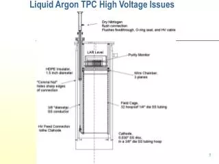
The HV Cage The Field shaping cage is made from 16 “barrel staves”, each 1.04 m wide by 4.1 m high, that carry the electrode pattern and the voltage divider resistor chains. Each end of each barrel stave attaches to one of the support rings. Liquid Argon Purity Demonstration
Barrel Stave Design The staves are built as box beams, not unlike airplane wings (for the same reason) to make a stiff yet light weight structure, as sketched below. The moon shaped inner area is occupied by periodic thin ribs. The ribs have tabs that penetrate the curved surfaces for a robust and self- aligned glue connection. Liquid Argon Purity Demonstration
The Top and Bottom Closure of the Pill Box The top and bottom caps need to meet several requirements: --Provide sufficiently closely spaced electrodes to achieve a uniform field --Must be reasonably open to LAr convection flow to achieve uniform Argon temperature and efficient and thorough circulation through the purifier --Avoid Sharp points and edges against field concentration --Must be installed as the last exit gate for the workers Liquid Argon Purity Demonstration
Pill Box End Design The present design uses a number of 1” diameter thin wall tubes, maybe titanium, that span up to nearly the full diameter. The tubes will sag less than 1” in the middle, which will cause negligible field distortions. The tubes are individually bolted to G10 “flags” that are formed by saw-cutting the ends of the staves to a depth of about 10 inches. The flags give a strong and stiff support to the tubes, but allow flexing as needed on cool down. The edges of the flags are covered with sections of copper tube to avoid excessive field concentrations. Liquid Argon Purity Demonstration
Electrical and Grounding Some observations : The signals are generated between the sense wires and the neighboring wires as well as cold tank. The current flow is completed through the dielectric (the LAr). The intrinsic noise is about 10% of the signal. No additional significant external noise is allowed. Noise is created by ac fields on the inner tank. By Ohm’s law such fields imply currents flowing in the cold tank walls. Ergo such currents must be kept to very low values in the frequency range of interest (100 kHz to 10 MHz) Liquid Argon Purity Demonstration
--Insulate the warm and cold tank from the ground --Insulate the cold tank from the warm tank, except at Chimneys (connections may be avoidable there as well). --Try to connect all potential noise conductors in a single point. The top of the cold tank is our approximation to the single point --Use bellows on pipes as convenient resistors --Use copper shunts between chimneys to short out noise currents --Use ceramic Rf chokes and Permalloy chokes around all pipes --Insulate pipes from the warm tank to prevent it from sending currents --Bring the inner tank reference out through the signal feed- throughs, rather than using the warm tank reference at the feed- throughs. How we Avoid Currents in the Cold Tank Wall Liquid Argon Purity Demonstration
Grounding Concept Liquid Argon Purity Demonstration
Tank and Anchor Insulation Liquid Argon Purity Demonstration
Chimney grounding Liquid Argon Purity Demonstration
Bottom Drain Pipe grounding Liquid Argon Purity Demonstration
Top LN2 Pipe grounding Liquid Argon Purity Demonstration
Safety Grounds and Lightning Protection Liquid Argon Purity Demonstration