Instruction Level Parallelism
This document explores the concepts of Instruction-Level Parallelism (ILP), detailing its definition, necessary conditions for overlap in instruction execution, and hardware architectures like Scoreboard and Tomasulo algorithms that exploit ILP. It emphasizes the importance of structural hazard management, dynamic scheduling, and out-of-order execution. The Scoreboard scheme is explained, highlighting its stages, implications for execution, and solutions for Write After Read (WAR) and Write After Write (WAW) hazards. An illustrative example demonstrates the Scoreboard's operation in practice.

Instruction Level Parallelism
E N D
Presentation Transcript
Instruction Level Parallelism 1. Scoreboard and Tomasulo algorithms
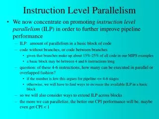
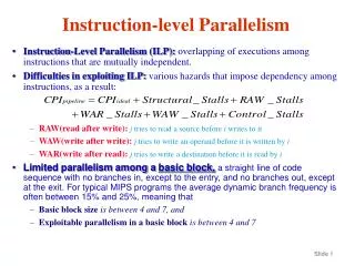
Definition of ILP • ILP=Potential overlap of execution among instructions. • Overlapping possible if: • No Structural Hazards • No RAW, WAR of WAW Stalls • No Control Stalls
Hardware Schemes to exploit ILP • Why? • Works when can’t know real dependence at compile time • Compiler Simpler • Code for one machine runs well on another
Key Idea: • Allow instructions behind stall to proceed • Enables out-of-order execution and completion (commit). • First implemented in CDC 6600 (1963).
Example: DIVD F0,F2,F4 ADDD F10,F0,F8 SUBD F12,F8,F14 • ADDD surely stalls for F0 (waiting that DIVD commits). • SUBD would stall without dynamic scheduling.
Scoreboard Scheme • Similar to the DLX scheme. • ID stage splitted in two parts: • Issue (decode and check structural h.). • Read Operands (wait until no data hazards). • Scoreboard allow instructions without dependencies to execute.
Scoreboard Implications • Out-of-order completion -> WAR and WAW hazards. • Solutions for WAR: • Queue both the operations and copies of its operands. • Read registers only during Read Operands stage.
Scoreboard Implications • For WAW, the machine stalls until the other instruction completes • Multiple execution units • Scoreboard keeps track of dependencies and state of operations.
Four Stages of Scoreboard Control • IssueDecode instructions & check for structural hazards.If a functional unit for the instruction is free and no other active instruction has the same destination register (WAW), the scoreboard issues the instruction to the functional unit and updates its internal data structure. If a structural or a WAW hazard exists, then the instruction issue stalls, and no further instructions will issue until these hazards are cleared.
Four Stages of Scoreboard Control 2. Read OperandsWait until no data hazards, then read operandsA source operand is available if: - no earlier issued active instruction will write it or - A functional unit is writing its value in a registerWhen the source operands are available, the scoreboard tells the functional unit to proceed to read the operands from the registers and begin execution.RAW hazards are resolved dynamically in this step, and instructions may be sent into execution out of order.
Four Stages of Scoreboard Control 3.ExecutionOperate on operandsThe functional unit begins execution upon receiving operands. When the result is ready, it notifies the scoreboard that it has completed execution.FUs are characterized by: - latency (the effective time used to complete one operation). - Initiation interval (the number of cycles that must elapse between issuing two operations to the same functional unit).
Four Stages of Pipeline Control 4. Write resultFinish executionOnce the scoreboard is aware that the functional unit has completed execution, the scoreboard checks for WAR hazards. If none, it writes results. If WAR, then it stalls the instruction.
WAR Example DIVD F0,F2,F4 ADDD F10,F0,F8 SUBD F8,F8,F14 In this case, the scoreboard would stall the SUBD in the WB stage,waiting that ADDD reads F0 and F8.
Scoreboard structure • Instruction status • Functional Unit statusIndicates the state of the functional unit (FU): Busy – Indicates whether the unit is busy or not Op - The operation to perform in the unit (+,-, etc.) Fi - Destination register Fj, Fk – Source register numbers Qj, Qk – Functional units producing source registers Rj, Rk – Flags indicating when Fj, Fk are ready • Register result status.Indicates which functional unit will write each register. Blank if no pending instructions will write that register.
Scoreboard Example Cycle 2 Integer Pipeline Full – Cannot exec 2nd Load – Issue stalls
Scoreboard Example Cycle 3 • Issue stalls
Scoreboard Example Cycle 4 • Issue stalls
Scoreboard Example Cycle 5 In this cycle the 2nd load is issued.
Scoreboard Example Cycle 6 • Mult is issued but has to wait for F2
Scoreboard Example Cycle 7 Now, Subd can be issued, but has to wait for operands.
Scoreboard Example Cycle 8a • DIVD is issued but there is another RAW hazard
Scoreboard Example Cycle 8b • Load completes, and operands for Mult and subd are ready
Scoreboard Example Cycle 9 MULT and SUB are sent in execution in parallel
Scoreboard Example Cycle 11 • The SUBD finishes
Scoreboard Example Cycle 12 • Read operands for DIVD?
Scoreboard Example Cycle 13 • SUBD writes results and ADDD can be issued
Scoreboard Example Cycle 17 • Write result of ADDD? NO, there is a WAR hazard
Scoreboard Example Cycle 22 Now DIVD can read its operands, ADDD can write the result
Scoreboard Example Cycle 61 • DIVD finishes,
CDC 6600 Scoreboard • Achieves a speedup of 2.5 w.r.t. no dynamic scheduling • By reorganizing instructions the compiler achieves only 1.7 • But • No cache • No forwarding hardware • Limited to instructions in a basic block • Small number of functional units (structural hazards) • Wait fo WAR hazards • Prevent WAW hazards
Tomasulo Algorithm • Invented at IBM 3 years after CDC 6600 for the IBM 360/91 • Same Goal: performance w/o special compilers • Lead to: • Alpha 21264, HP 8000, MIPS 10000, Pentium II, PowerPC 604
Tomasulo Algorithm Basics • The control logic and the buffers are distributed with Fus • Operand buffers are called reservation stations. • Each instruction is an entry of a reservation station. • Its operands are replaced by values or pointers (Register Renaming)
Tomasulo Algorithm Basics • Register Renaming allows to: • Avoid WAR and WAW hazards • Reservation stations are more than registers (so can do better optimizations than a compiler). • Results are dispatched to other Fus through a Common Data Bus • Load/Stores treated as FUs
Reservation Station Components • Tag identifying the RS • OP=the operation to perform on the component. • Vj, Vk=Value of the source operands • Qj,Qk=Pointers to RS that produce Vj,Vk • Busy=Indicates RS Busy
Other components • RF and the Store buffer have a Value (V) and a Pointer (Q) field. • Load buffers have an address field, and a busy field. • Store Buffers have also an address field.
The three stages of the Tomasulo Algorithm. • ISSUE.Get an instruction I from the queue. If it is an FP op. Check if an RS is empty (i.e., check for structural hazards).Rename registers; WAR resolution: If I writes Rx, read by an instruction K already issued, K knows already the value of Rx or knows what instruction will write it. So the RF can be linked to I.WAW resolution: Since we use in-order issue, the RF can be linked to I.
The Three Stages of The Tomasulo Algorithms • ExecutionWhen both operands are ready then execute. If not ready, watch the common data bus fo results • Write resultWrite on Common Data Bus to all waiting units; mark reservation stations available.
The Common Data Bus • A common data bus is a data+source bus. • In the IBM 360/91Data=64 bits, Source=4 bits • FU must perform associative lookup in the RS.
Pipelined FUs Issue window size=14 No issue on structural hazards WAR, WAW avoided with renaming Broadcast results from FU Control distributed on RS Multiple but not pipelined Fus Issue window size=5 No issue on structural hazards Stall the completion for WAW and WAR hazards Results written back on registers. Control centralized through the Scoreboard. Tomasulo (IBM) versus Scoreboard (CDC)