Setting Up a New Survey Project in AutoCAD: Step-by-Step Guide
This detailed guide walks you through creating a new drawing project in AutoCAD, focusing on setting up a survey project from scratch. You will learn how to define project settings, choose drawing scales, and manage data collection and transfer using the software. We will cover importing data, creating point groups, and generating contour lines to visualize terrain models effectively. Ideal for surveyors and civil engineers looking to enhance their skills in AutoCAD.

Setting Up a New Survey Project in AutoCAD: Step-by-Step Guide
E N D
Presentation Transcript
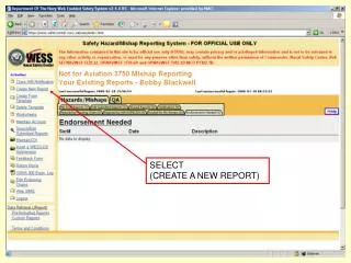
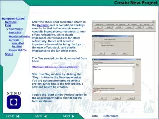
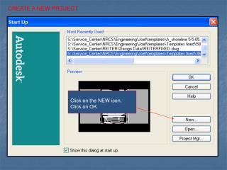
CREATE A NEW PROJECT Click on the NEW icon. Click on OK
AutoCad opens with a blank screen. At the command line type NEW.
Type in the name of the drawing. Click CREATE PROJECT
Name the Project Click OK
You can click on a setting set and click on FINISH or Choose NEXT to alter the standard setting set for that scale.
If you choose NEXT, a series of dialogue boxes will enable you to alter settings of your drawing setup.
Choose an appropriate drawing scale, and sheet size. Choose NEXT.
Appropriate coordinate zones can be selected. This can also be left as NONE, if you do not need to tie into specific zones. Select NEXT.
Text styles and sizes can be selected here. Leroy is generally used. If you select standard sizes, text sizes will be set in text format. Select NEXT.
You can select a border, it is not necessary and can be added later. Select NEXT.
This generates a dialogue box with all the selected settings for your review. Click OK.
Select ACAD and Workspaces
Set your Workspaces toolbar where ever it fit on your screen. Click on the arrow and select Survey.
A default screen will appear. Close these toolbars by clicking on the X’s.
With the RECEIVE tab active, select SEQUENTIAL. Check GET FILE… Select the type of Data collector you are using.
Still in the same screen, select CHOOSE DIRECTORY. Choose the SURVEY portion of the drawing you just set up. • Click OK. • Click RECEIVE.
This screen will appear and will inform if transfer was successful. Close box.
The data must be converted from the .CR5 format that it was imported to a Fieldbook format. Check COORDINATE FILE. Imput type=TDS COORDINATES. Select CHOOSE FILE. Under Survey in the appropriate file the .CR5 file you just imported should be listed. Click OPEN.
On the lower half of the screen, select AutoDesk Softdesk FBK with Linework. • Select CHOOSE FILE (this is where you are storing the Fieldbook.) • Name the file with .fbk extension. • Click SAVE.
Still no survey? Under Data Collection/Input select IMPORT FIELD BOOK.
Find where you saved the field book and highlight the .fbk file you just created and click OPEN.
A series of 4 questions will be on the command line. Answer them (NO) in this case. Click RETURN after each.
Still no survey data? Type Z (for Zoom)
Many Options! Type E (for extents)
TA DA! The survey data should appear.
Now we want to create a surface, but before we have to create a point group. From Points select Point Management and then Point Group Manager.
From the icons in the upper left corner click on the first one to the left. CREATE POINT GROUP
Name the point group. Highlight the INCLUDE tab. Identify which points you want included in the surface. You can do this by checking the INCLUDE ALL POINTS box. If there are points you do not want, from here you can check the EXLUDE tab and remove the individual points you do not want on the surface. An example would be if you do not want the bench mark shot on the surface because it is above the ground, it can be removed. Select OK
The point group manager dialogue box will appear with all of the points to verify it. Shut it off.
HOW TO INSTALL CONTOUR LINES To create contour lines, you must create a surface with the point data you just loaded. With current survey open, select TERRAIN MODEL EXPLORER from the TERRAIN menu.
Right Click on TERRAIN. Left Click on CREATE NEW SURFACE.
Sign to open options. • Right Click on POINT GROUPS. • Left Click on ADD A POINT GROUP.
Right Click on SURRFACE. Select BUILD
If all goes well, You should see this. Select OK.
This dialogue box confirms the Surface Statistics of the surface, including the point data, which we just created. Confirm statistics, and shut the box off.
The contours here are very abrupt. The style can be smoother. Also labels can be applied to the contours globally. The text height can be set.