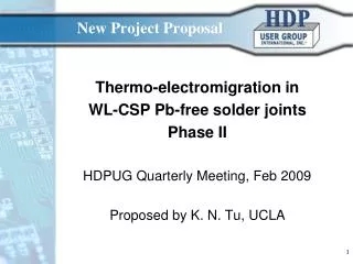
New Project Proposal
This proposal aims to address the critical issue of thermo-electromigration-induced failures in ball grid array (BGA) Pb-free solder joints. Given the industry's shift away from lead-based solders and the increasing demand for miniaturization in electronics, understanding the reliability of Pb-free interconnections is paramount. This project will explore mean-time-to-failure (MTTF) for different doped SnAgCu solders under controlled thermal and electrical conditions, advancing experimental setups to enhance data analysis and improve failure predictions.

New Project Proposal
E N D
Presentation Transcript
New Project Proposal Thermo-electromigration in WL-CSP Pb-free solder joints Phase II HDPUG Quarterly Meeting, Feb 2009 Proposed by K. N. Tu, UCLA
Purpose • Reduce thermo-electromigration induced failure in WL-CSP Pb-free flip solder joints • Owing to the ban of Pb-based solder in consumer electronic products and the trend of miniaturization in wireless and portable devices, the reliability of Pb-free solder interconnection is one of the most challenging problems in electronic manufacturing industry, especially the failure causes by thermo-electromigration. Joule heating due to the on-chip Al interconnect has generated thermomigration to accompany electromigration in solder joints. For a joint of 200 micron in size, a temperature difference of 20 C across it will cause a temperature gradient of 1000 C/cm, which can lead to thermomigration. We define the combined effect as thermo-electromigration. • This proposal is to continue the previous project supported by HDP in 2008. There are two parts; the first one is for six months, and the second one is for one year.
Objective • To determine mean-time-to-failure (MTTF) of thermo-electromigration in SnAgCu solders of low Ag with different dopants and different UBM at two current densities of 5 x 10³ and 1 x 10⁴ A/cm2 and at two temperatures of 125 and 150 °C • The figure on next foil shows the experimental set-up at UCLA for electromigration testing of flip chip SAC sample. We can apply two current densities and at two temperatures. • In the set-up for the combination of two current densities and at two temperatures, we have measured in each set 4 boards together, each board has 4 chip, and each chip has 36 flip chip solder joints (of which 2 can be electrically tested for thermo-electromigration and 1 can be electrically tested for thermomigration effects only). So we have obtained statistical distribution of failure. • Weibull distribution has been used to analyze the data. We determined the activation energy as well as the current density exponential factor. MTTF equation has been obtained. (see the Final Report submitted for the 2008 project).
Experimental Setup (I) Power supply: I1, I2, I1, I2 Furnace 1: 150 C Furnace 2: 125 C USB data collection I1: 3.14A (104A/cm2), I2: 1.57A (5 x 10³A/cm2)
Technical discussion • In this project, so far we have studied mainly the failure due to thermo-electromigration. We have obtain MTTF equation on the basis of two current densities and two temperatures. • To have a better fit to Black’s equation, we need to test at the least one more temperature and one more current density. • We have not studied thermomigration. While we have studied the combined effect of electromigration and thermomigration on failure. We need to decouple them. • In electromigration tests of flip chip solder joints, there are two factors which affects the MTTF analysis; one is the effect of current crowding due to the line-to-bump configuration, and the other is joule heating induced thermomigration which accompanies electromigration. We have studied the former, but not the latter. • It is proposed here to have a one-year project so that we can have more data for better fitting of Black’s equation and also to study thermomigration. • Alternatively, a six-month proposal is also presented to complete the on-going work.
On-going Work • We are running the rest of the tests at current density of 5 x 10³ A/cm2 and at 125 and 150 °C. It will take at the least 2 to 3 months to finish them. • We are also running AlNVCu/SAC1205 samples at 100 °C with current density at 1 x 10⁴ A/cm2. It may take 3 to 6 months to finish it.
Black’s Equation Fit to the AlNiVCu/SAC1205 data(180°C to 155°C at 5,000A/cm2 to 10,000A/cm2) • SN100C: Sn (R), Cu, 0.65%, Ni, 500ppm, Ge 60ppm, Bi 110ppm, Pb 140 ppm • SAC1205: Sn(R), Ag 1.2%, Cu 0.5%
Proposed work for Jan to June 2009 • On-going work (to be finished in January to June, 2009) • ● Electromigration Tests of the 6 experimental Legs: • 5,000A/cm2@150C ambient testing • 5,000A/cm2@125C ambient testing • 10,000A/cm2@100C ambient for Leg 8, testing. • ● Ball Impact Toughness after Annealing at 180C for • 24 hrs and 72 hrs. • ● FIB/SEM examination of failed samples in the 6 experimental Legs (examples are shown in the next two foils for the TiCuCu/SN100C experimental leg).
Kirkendall voids Pancake void Sn IMC Cu, Al Void in Al trace Failure analysis by FIB
Kirkendall voids Cu-2 Pancake void Cu-1 Al Cu6Sn5 Cu3Sn Scanning Ion Tunnelling Image
Six-month Project Plan Cost: $20,000 01/01/09 – 03/31/09 (Y2Q1) • Electromigration tests as a function of low current density of 5 x 10³ A/cm2, time and temperature. Cross-section of failed samples at higher current density prepared by FIB and SEM. 04/01/09 – 06/30/09 (Y2Q2) • Electromigration experiment tests continue as a function of current density, time and temperature. To confirm the mode of failure so that we can confirm the test parameters for MTTF. • Complete the failure analysis, complete project report, and prepare journal publications. • Do additional experimental testing to quantify the thermomigration and stressmigration effects. If these effects are deemed to be significant, consider whether the project can be extended for another 6 months to run 3D FEM modeling quantifying the individual effects of electromigration, thermomigration and stressmigration. (The cost to extend the project for this additional 6 months will be $25,000 in order to hire a post-doc to assist with the computer modeling and to do the additional experimental verification work.)
Proposed work for Jan. to Dec., 2009 • Finish the on-going work ($10,000 per Quarter for Q1 and Q2) • Electromigration Tests of all 6 experimental Legs • Two current densities of 5 x 10³ A/cm2 and 1 x 10⁴ A/cm2 • Two temperatures of 125 °C and 150 °C • Ball Impact Toughness after Annealing(24 hrs and 72 hrs@180C) • FIB of cross-sections of the all 6 experimental Legs. New proposed work ($10,000 per Quarter for Q3 and Q4) • Electromigration Testing of all 6 experimental Leg at2 x 104 A/cm2 and 100 °C • FIB/SEM examination of all failed samples • MTTF analysis over these wider experimental conditions. • Decoupled Electromigration, Thermomigration, Stressmigration Testing • If Thermomigration and/or Stressmigration are deemed to be significant, hire a post DOC to do 3D finite element modeling to quantify the magnitudes these effects ($12,500 per Quarter for Q3 and Q4 if 3D modeling is added).
One-year Project Plan 01/01/09 – 03/31/09 (Y2Q1) ● Continue electromigration tests as a function of low current density of 5 x 10³ A/cm2, time and temperature. Cross-section of failed samples at higher current density prepared by FIB and SEM. Start electromigration tests at 100 °C of high current density of 2 x 10⁴ A/cm2. 04/01/09 – 06/30/09 (Y2Q2) ● Electromigration experiment tests continue as a function of current density, time and temperature. Start thermomigration tests to examine un-powered neighboring solder joint. FIB and SEM cross-section samples prepared. Project Costs for Q1 and Q2: $10,000 per quarter (to finish the current work). 07/01/09 to 09/31/09 (Y2Q3) ● Confirm the mode of failure of electromigration, so that we can confirm the test parameters for MTTF. Decouple the effect of electromigration and thermomigration on failure. To determine the failure mode of thermomigration. 10/01/09 to 12/31/09 (Y2Q4) ● To finalize MTTF equation and to determine the activation energy and exponential factor of current density for Leg 1 to Leg 8 samples. Complete the failure analysis, complete project report, and prepare journal publications. Project Cost for Q3 and Q4: If significant thermo-migration or stress-migration effects can be detected in Q1 and Q2 of this project, Prof. Tu would like to hire a post-doc to assist with 3d FEM modeling to quantify the magnitudes of the 1) electro-migration, 2) thermo-migration and 2) stress-migration effects. This would increase the costs for Q3 and Q4 to $12,500 per quarter.
Resources and Requests • UCLA has been supported by NSF, SRC, NSC, and Intel over the last ten years to study electromigration in flip chip solder joints. We have built two sets of test stages with multi-channel control to perform large scale electromigration tests, so we can obtain statistical distribution of failure. Also we have FIB and SEM for imaging and e-beam probe for composition analysis. • We have access, in Taiwan, to 3-D FEA simulation of current distribution, joule heating, and temperature distribution in flip chip solder joints, including Al interconnect and under-bump-metallization. • Project Updates to be preformed on a bi-monthly basis. • To perform the proposed work, the support of one M. Sc. student for six months at $20,000 or for a year at $40,000 is requested (or $45,000 if a post-doc for 3D FEA is hired).
“Lead-Free and PbSn Bump Electromigration Testing.” Stephen Gee, Nikhil Kelkar, Joanne Huang and King-Ning Tu, IPAC2005 National Semiconductor & UCLA Experimental Results: LEFT: Chart showing the improved performance of SnAgCu over eutectic PbSn at 1.7 Amps and 150°C. RIGHT: Cross-Section of SnAgCu after 1475 Hours at 1.8A and 150°C (Right)
“Modeling of electromigration combined with thermal–mechanical effect for IC device and package”, Yong Liu, Lihua Liang, Scott Irving, and Timwah Luk, Microelectronics Reliability, 2008. Fairchild & Zhejiang University 3D modeling of maximum atomic flux divergence due to electro-migration, thermo-migration and stress-migration indicate that SnAgCu should perform better than eutectic PbSn. Predicted Void Formation for SnAgCu after 1074.6 hr at 1.8A and 150C.
Team Liaison NSC – Stephen Gee HDP – Marshall Andrews Others are welcome to join.