Chapter 1 INTRODUCTION TO SEMICONDUCTORS MATERIAL
1.42k likes | 2.47k Vues
Chapter 1 INTRODUCTION TO SEMICONDUCTORS MATERIAL. Prepared By: Mrs Nur Baya Binti Mohd Hashim School of Computer and Communication Engineering UNIMAP. Objectives. Discuss basic structures of atoms. Discuss properties of insulators, conductors, and semiconductors.

Chapter 1 INTRODUCTION TO SEMICONDUCTORS MATERIAL
E N D
Presentation Transcript
Chapter 1INTRODUCTIONTOSEMICONDUCTORS MATERIAL Prepared By: Mrs Nur Baya Binti Mohd Hashim School of Computer and Communication Engineering UNIMAP
Objectives • Discuss basic structures of atoms • Discuss properties of insulators, • conductors, and semiconductors • Discuss covalent bonding • Describe the conductions in semiconductor • Discuss N-type and P-type semiconductor • Discuss the diode • Discuss the bias of a diode
LECTURE’S CONTENT 1.1Atomic structure 1.2 Semiconductor, conductors and insulators 1.3 Covalent bonding 1.4 Conduction in semiconductors 1.5 N-type and P-type semiconductors 1.6 Diode 1.7 Biasing the diode 1.8 Voltage-current characteristic of a diode 1.9 Diode models 1.10 Testing a diode
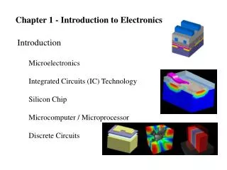
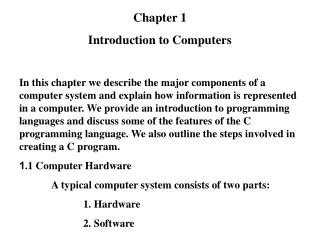
INTRODUCTION • Radio • Television • Computer • Telephone Electronic Systems Vacuum Tubes Vacuum Tube 1890s Amplifier Rectifier Able to operate very well • Large • Fragile • High power consumption To convert ac energy to dc energy To increase the strength of ac signals
INTRODUCTION Fig.1: Structure of a vacuum tube diode and triode
Transistor 1950s • Smaller • More rugged • Less power consumption A Semiconductor Device commonly used as an amplifier or an electrically controlled switch Single small chip μicro-Processors 1980s Integrated circuits 1960s INTRODUCTION
PNP P-channel NPN N-channel BJT JFET INTRODUCTION Fig. 2: Transistor and symbols BJT = Bipolar Junction transistor JFET = Junction Field-Effect Transistor
INTRODUCTION (a) (b) Fig. 3: (a) Integrated circuits and (b) microprocessor A microprocessor is a programmabledigitalelectronic component that incorporates the functions of a central processing unit (CPU) on a single semiconductingintegrated circuit (IC).
1.1 Atomic Structure Atomic number Basic structure Electron shells ATOM Valence electron Free electron Ionization
1.1 Atomic Structure The Atom • Atom is the smallest particle of an element that retains the characteristics of that element. • An atom consists of the protons and neutrons that make up the nucleus (core) at the center and electrons that orbit about the nucleus. • The nucleus carries almost the total mass of • the atom. • Neutrons are neutral and carry no charge. • Protonscarry positive charges. • The electrons carry negative charges. • The number of protons = the number of electrons in an atom, which makes it electrically neutral or balanced. Fig. 4: Bohr model of an atom
1.1 Atomic Structure (cont.) Protons (positive charge) Electrons (negative charge) ATOM Nucleus (core of atom) Neutrons (uncharged)
1.1 Atomic Structure (cont.) • Atomic Number - Element in periodic table are arranged according to atomic number • Atomic number = number of protons in nucleus which is the • same as the number of electron in an electrically balanced atom • Electron Shells and Orbits • Electrons near the nucleus have less energy than those in more • distant orbits. • Each distance (orbits) from the nucleus corresponding to a • certain energy level. • In an atom, the orbits are group into energy bands – shells • Diff. in energy level within a shell << diff. in energy between • shells.
1.1 Atomic Structure (cont.) L K N M - - - - - - - - - - - - 29 p - - - - - Shells or orbital paths + - - 29 n Valence Electron Valence shell is the outermost shell in an atom that determines the conductivity of an atom. The electrons in valence shell are called valence electrons. - - - - - - - - - - Valence electron Valence shell Fig.5: Bohr model of copper atom (Cu)
1.1 Atomic Structure (cont.) • The Number of Electrons in Each Shell • The maximum number of electrons (Ne) ineach shell is calculated using formula below: • n = number of shell • Example for the copper atom (Cu) shell : 1st shell (K): 2n2 = 2(1)2 = 2 electrons 2nd shell (L): 2n2 = 2(2)2 = 8 electrons 3rd shell (M): 2n2 = 2(3)2 = 18 electrons 4th shell (N): 1 electrons Total: 29 electrons n = the shell number
1.1 Atomic Structure (cont.) • Ionization • When atom absorb energy (e.g heat source) the energies of the electron are raised • Valence electron obtain more energy and more loosely bound to the atom compared to the inner electron • If a valence electron acquires sufficient energy – escape from the outer shell and the process of losing valence electron called ionization. • The escape electron is called free electron.
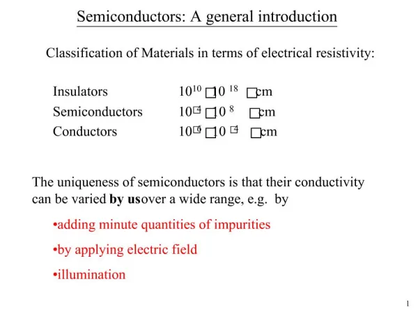
In terms of electrical properties Materials Insulators Conductors Semiconductors All materials are made up of atoms that contribute to its ability to conduct electrical current 1.2 Semiconductors, Conductors, and Insulators
1.2 Semiconductors, Conductors, and Insulators • Atom can be represented by the valence shell and a core • A core consists of all the inner shell and the nucleus Example of carbon atom: -valence shell = - 4 e -inner shell = - 2 e Nucleus: = 6 protons = 6 neutrons +6 for the nucleus and -2 for the two inner-shell electrons (net charge +4) Fig. 6: Diagram of a carbon atom
1-2 Semiconductors, Conductors, and Insulators (cont.) • Conductors • material that easily conducts electrical current. • The best conductors are single-element material (e.g copper, silver, gold, aluminum) • Only one valence electron very loosely bound to the atom- free electron • Insulators • material does not conduct electrical current (e.g rubber, plastic) • valence electron are tightly bound to the atom – very few free electron • Semiconductors • material between conductors and insulators in its ability to conduct electric current • in its pure (intrinsic) state is neither a good conductor nor a good insulator • most common semiconductor-silicon(Si), germanium(Ge), and carbon(C) which contains four valence electrons.
1.2 Semiconductors, Conductors, and Insulators (cont.) Energy Energy Conduction band Conduction band E4 = 1.8eV Energy gap E3 = 0.7eV Valence band E2 E1 Second band (shell 2) E = energy level Valence band First band (shell 1) Nucleus Energy Bands Fig. 1-6: Energy band diagram for an unexcited (no external energy) atom in a pure (intrinsic) Si crystal.
1-2 Semiconductors, Conductors, and Insulators (cont.) Energy Bands Fig. 7: Energy diagram for three types of materials • Energy gap-the difference between the energy levels of any two orbital shells • Band-another name for an orbital shell (valence shell=valence band) • Conduction band –the band outside the valence shell where it has free electrons.
1-2 Semiconductors, Conductors, and Insulators (cont.) • Comparison of a Semiconductor Atom to a Conductor Atom • Core of Si atom has a net charge of +4(14 protons – 10 electrons) and • +1(29 protons – 28 electrons) for Cu atom. • A valence electron in Si atom feels an attractive force of +4 compared to Cu • atom which feels an attractive force of +1. • Force holding valence electrons to the atom in Si > in Cu. • The distance from its nucleus of Copper’s valence electron (in 4th shell) > • silicon’s valence electron (in 3rd shell).
1-2 Semiconductors, Conductors, and Insulators (cont.) Valence electrons Valence electrons Core (+4) Core (+1) (a) Silicon atom (a) Copper atom Fig.1-10: Diagrams of the silicon and copper atoms
1-3 Covalent Bonding 1-3 Covalent Bonding Covalent bonding – holding atoms together by sharing valence electrons sharing of valence electron produce the covalent bond To form Si crystal
1-3 Covalent Bonding (cont.) • Result of the bonding: • The atom are held together forming a solid substrate. • The atoms are all electrically stable, because • their valence shells are complete. • The complete valence shells cause the silicon to act as an insulator-intrinsic (pure) silicon. • In other word, it is a very poor conductor.
1-3 Covalent Bonding (cont.) • Covalent bonding in an intrinsic or pure silicon crystal. An intrinsic crystal has no impurities. Covalent bonds in a 3-D silicon crystal
1-4 Conduction in Semiconductor Figure 1-10 Energy band diagram for a pure (intrinsic) silicon crystal with unexcited (no external energy such as heat) atoms. There are no electrons in the conduction band. This condition occurs only at a temperature of absolute 0 Kelvin.
1-4 Conduction in Semiconductor • Conduction Electrons and Holes • When an electron jumps to the conduction band, a vacancy is left in the vallence band, this vacancy is called a hole and the electron is said to be in an excited state. • Recombination occurs when a conduction-band electron after within a few microseconds of becoming a free, loss its energy and falls back into a hole in the valence band. • The energy given up by the electron is in the form of light and/or heat. Fig.1-11: Creation of electron-hole pairs in a Si atom. (a) energy diagram, and (b) bonding diagram
1-4 Conduction in Semiconductor Electron Current At the temperature room, at any instant, a number of free electrons that are unattached to any atom drift randomly throughout the material. This condition occurs when no voltage is applied across a piece of intrinsic Si (as illustrated in Fig. 12). When a voltage is applied across the piece of intrinsic Si, as shown in Fig. 13, the thermally generated free electrons in the conduction band, which are free to move, are now easily attracted toward the positive end. The movement of free electrons in a semiconductive material is called electron current.
1-4 Conduction in Semiconductor Fig .12: Free electrons are being generated continuously while some recombine with holes
1-4 Conduction in Semiconductor Hole Current At the same time, there are also an equal number of holes in the valence band created by electrons that jump into the conduction band (Fig. 13). Electron remaining in the valence band are still attached to the atom – not free to move like free electron. However, valence electron can move into nearby hole – leaving another hole it comes from Thus, hole has moved from one place to another in the opposite direction. The movement of electrons in a valence band is called hole current.
1-4 Conduction in Semiconductor Fig. 13: Free electrons are attracted toward the positive end
1-4 Conduction in Semiconductor (cont.)Electrons and Holes Current movement of holes Figure 14 Hole current in intrinsic silicon.
1-5 N-type and P-type Semiconductors Doping - The process of creating N and P type materials - By adding impurity atoms to intrinsic Si or Ge to improve the conductivity of the semiconductor - Two types of doping – trivalent (3 valence e-) & pentavalent (5 valence e-) p-type material – a semiconductor that has added trivalent impurities n-type material – a semiconductor that has added pentavalent impurities • Trivalent Impurities: • Aluminum (Al) • Gallium (Ga) • Boron (B) • Indium (In) • Pentavalent Impurites: • Phosphorus (P) • Arsenic (As) • Antimony (Sb) • Bismuth (Bi)
1-5 N-type and P-type Semiconductors (cont.) Energy Conduction band - - - - - - - - - - - - - - - - - - - - - - - Electrons (majority carriers) Valence band Holes (minority carriers) • N-type semiconductor • Pentavalent impurities are added to Si or Ge, • the result is an increase of free electrons • 1 extra electrons becomes a conduction • electrons because it is not attached to any • atom • No. of conduction electrons can be controlled • by the no. of impurity atoms • Pentavalent atom gives up (donate) an • electron - call a donor atom • Current carries in n-type are electrons – • majority carriers • Holes – minority carriers (holes created in Si • when generation of electron- holes pair. Sb impurity atom Fig (a) Fig. (a): N-type semiconductor Fig. (b) : Energy diagram (n-type) Fig (b)
1-5 N-type and P-type Semiconductors (cont.) • P-type semiconductor: • Trivalent impurities are added to Si or • Ge to increase number of holes. • Boron, indium and gallium have 3 • valence e- form covalent bond with 4 • adjacent silicon atom. A hole created • when each trivalent atom is added. • The no. of holes can be controlled by • the no. of trivalent impurity atoms • The trivalent atom can take an • electron-acceptor atom • Current carries in p-type are holes – • majority carries • Electrons – minority carries (created • during electron-holes pairs generation). B impurity atom Fig (a) Fig. (a): P-type semiconductor Fig. (b) : Energy diagram (p-type) Fig (b)
1-6 The Diode • - Diode is a device that conducts current only in one direction. • - n-type material & p-type material become extremely useful when • joined together to form a pn junction – then diode is created • Before the pn junction is formed -no net charge (neutral) since no of proton and electron is equal in both n-type and p-type. • p region: holes (majority carriers), e- (minority carriers) • -n region: e- (majority carriers), holes (minority carriers)
1-6 The Diode (cont.)The Depletion Region • Summary: • When an n-type material is joined with a p-type material: • A small amount of diffusion occurs across the junction. • When e- diffuse into p-region, they give up their energy and fall into the holes near the junction. • Since the n-region loses electrons, it creates a layer of +ve charges (pentavalent ions). • p-region loses holes since holes combine with electron and will creates layer of –ve charges (trivalent ion). These two layers form depletion region. • Depletion region establish equilibrium (no further diffusion) when total –ve charge in the region repels any further diffusion of electrons into p-region.
1-6 The Diode (cont.)The Depletion Region - - - - - - +4 +4 +4 +4 +3 +4 +4 +4 +4 +5 - - - - - - - - - - - - - - - - - - - - - - - - - - - - - - - - - - Junction P-type N-type Total (+) = 19 Total (-) = 20 Net charge = -1 Total (+) = 21 Total (-) = 20 Net charge = +1 Fig.1-18: Depletion layer charges
1-6 The DiodeBarrier Potential • In depletion region, many +ve and –ve charges on opposite sides of pn junction. • The forces between the opposite charges form a “field of forces "called anelectric field. • This electric field is a barrier to the free electrons in the n-region, therefore it needs more energy to move an e- through the electric field. • The potential difference of electric field across the depletion region is the amount of voltage required to move e- through the electric field.This potential difference is called barrier potential. [ unit: V ] • Depends on: type of semicon. material, amount of doping and temperature. (e.g : 0.7V for Si and 0.3 V for Ge at 25°C).
1-6 The Diode (cont.)Energy Diagram of the PN Junction and Depletion Region Overlapping
1-6 The Diode (cont.)Energy Diagram of the PN Junction and Depletion Region • Energy level for n-type (Valence and Cond. Band) << p- type material (difference in atomic characteristic : pentavalent & trivalent) and significant amount of overlapping. • Free e- in upper part conduction band in n-region can easily diffuse across junction and temporarily become free e- in lower part conduction band in p-region. After crossing the junction, the e- loose energy quickly & fall into the holes in p-region valence band.
1-6 The Diode (cont.)Energy Diagram of the PN Junction and Depletion Region • As the diffusion continues, the depletion region begins to form and the energy level of n-region conduction band decreases due to loss of higher-energy e- that diffused across junction to p-region. • Soon, no more electrons left in n-region conduction band with enough energy to cross the junction to p-region conduction band. • Figure (b), the junction is at equilibrium state, the depletion region is complete and diffusion has ceased (stop). Create an energy gradient which act as energy ‘hill’ where electron at n-region must climb to get to the p-region • The energy gap between valence & cond. band – remains the same