Understanding Chip Power Limits with CO2 Cooling: A Guide for Designers
This presentation by Brian Maynard from the SU HEP group explores the unknowns surrounding chip power limits when utilizing CO2 cooling. It serves as a guide for chip designers to understand the power they can afford under specific conditions. The study examines material properties, such as thermal conductivity and cooling schemes, while addressing the digital and analog sections of the chip. The findings aim to inform future chip designs and improve thermal management solutions, particularly in environments requiring efficient cooling strategies.

Understanding Chip Power Limits with CO2 Cooling: A Guide for Designers
E N D
Presentation Transcript
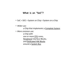
What is the Chip Power? Brian Maynard SU HEP GROUP
No one knows yet! • These slides will hopefully act as a guide for the chip designers to let them know what type of power we can afford to have with CO2 cooling
3 13 15 45 2 15
Cooling Scheme For right now the cooling is applied in the model on top of a 5 mm thick layer of glue with k =1 W/mK at the outer perimeter of the diamond layer (~4 cm from edge of silicon)
Including Digital Section of Chip 0.5 W/chip Analog +1/R section of chip (RDP) Constant digital section of chip (DPB) The orange part of the chip is situated such that it is farthest away from the beam center
SummaryCooling at -35C Cooling applied from sides at 1.0cm from Silicon and from back at 1.5cm