Inductors
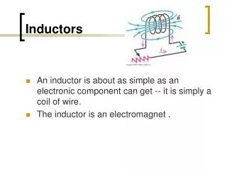
DC/AC Fundamentals: A Systems Approach. Inductors. Thomas L. Floyd David M. Buchla. Chapter 11. Ch.11 Summary. The Basic Inductor. When a length of wire is formed into a coil., it becomes an inductor. When there is current in the inductor, a three-dimensional magnetic field is created.

Inductors
E N D
Presentation Transcript
DC/AC Fundamentals: A Systems Approach Inductors Thomas L. Floyd David M. Buchla Chapter 11
Ch.11 Summary The Basic Inductor When a length of wire is formed into a coil., it becomes an inductor. When there is current in the inductor, a three-dimensional magnetic field is created. A change in current causes the magnetic field to change. This in turn induces a voltage across the inductor that opposes the original change in current. S N
Ch.11 Summary The Basic Inductor One henry (H) is the inductance of a coil when a current, changing at a rate of one ampere per second, induces one volt across the coil. Most coil values are far less than 1 H. Large inductors and transformers are wound around an iron core to increase inductance. Iron core
Ch.11 Summary Faraday’s Law The voltage induced in a coil is directly proportional to the rate of change of the magnetic field with respect to the coil.
Ch.11 Summary Lenz’s Law When the current through a coil changes, an induced voltage is created as a result of the changing magnetic field. The direction of the induced voltage is such that it always opposes the change in the current.
Ch.11 Summary Lenz’s Law A basic circuit to demonstrate Lenz’s law is shown. Initially, the SW is open and there is a small current in the circuit through L and R1.
Ch.11 Summary Lenz”s Law SW closes and immediately a voltage appears across L that tends to oppose any change in current. Initially, the meter reads same current as before the switch was closed.
Ch.11 Summary Lenz’s Law After a time, the current stabilizes at a higher level (due to I2) as the voltage across the coil decays. Later, the meter reads a higher current because of the load change.
Ch.11 Summary Inductor Characteristics In addition to inductance, inductors have winding resistance (RW), which is the resistance of the wire, and winding capacitance (CW) between the turns. An equivalent circuit for a practical inductor that includes these effects is shown: Notice that the winding resistance is in series with the coil and the winding capacitance is in parallel with both.
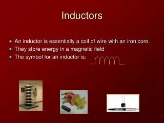
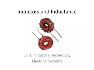
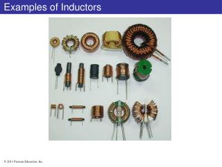
Ch.11 Summary Types of Inductors There are a variety of inductors, depending on the amount of inductance required and the application. Some, with fine wires, are encapsulated and may appear like a resistor. Common symbols for inductors (coils) are Air core Iron core Ferrite core Variable
Ch.11 Summary Factors Affecting Inductors Four factors affect the amount of inductance for a coil. The equation for the inductance of a coil is where L = inductance in henries N = number of turns of wire m = permeability in Wb/At-m l = coil length in meters
Ch.11 Summary Example What is the inductance of a 2 cm long, 150 turn coil wrapped on an low carbon steel core that is 0.5 cm diameter? The permeability of low carbon steel is 2.5 x10⁻⁴ H/m (Wb/At-m). 22 mH
Ch.11 Summary Common Inductors Inductors come in a variety of types and sizes. A few common ones are illustrated here.
Ch.11 Summary Series Inductors When inductors are connected in series, the total inductance is the sum of the individual inductors. The general equation for inductors in series is If a 1.5 m inductor is connected in series with an 680 mH inductor, the total inductance is 2.18 mH
Ch.11 Summary Parallel Inductors When inductors are connected in parallel, the total inductance is smaller than the smallest one. The general equation for inductors in parallel is The total inductance of two inductors is …or you can use the product-over-sum rule.
Ch.11 Summary Parallel Inductors The total inductance in the parallel circuit shown is 468 mH
Ch.11 Summary Inductors in DC Circuits Vinitial When an inductor is connected in series with a resistor and a dc source, current changes at an exponential rate. Ifinal
Ch.11 Summary Inductors in DC Circuits VS Exponential waveforms are also generated when a square wave source is connected to a series RL circuit. VL VR
Ch.11 Summary Universal Exponential Curves Rising exponential Falling exponential The exponential curves show how the current in an RL circuit increases (or decreases) over five equal periods, called time constants. For an RL circuit, the length of a time constant is
Ch.11 Summary Universal Exponential Curves The universal curves can be applied to general formulas for the current (or voltage) curves for RL circuits. The general current formula is • where • IF = final value of current • Ii = initial value of current • i = instantaneous value of current • e = Napier’s constant (approximately 2.71828) • The final current is greater than the initial current when the inductive field is building, and less than the initial current when the field is collapsing.
Ch.11 Summary Inductive Reactance Inductive reactance (XL) is the opposition of an inductor to alternating current (ac). The equation for inductive reactance is The reactance of a 33 mH inductor that is operated at 550 kHz is 114 W
Ch.11 Summary Inductive Reactance When inductors are in series, the total reactance is the sum of the individual reactances. That is, Assume three 220 mH inductors are in series with a 455 kHz ac source. What is the total reactance? The reactance of each inductor is 1.89 kW
Ch.11 Summary Inductive Reactance When inductors are in parallel, the total reactance is the reciprocal of the sum of the reciprocals of the individual reactances. That is, If the three 220 mH inductors from the last example are placed in parallel with the 455 kHz ac source, what is the total reactance? The reactance of each inductor is 629 W. Using these values: 210 W
Ch.11 Summary Inductive Phase Shift When a sine wave is applied to an inductor, there is a phase shift between voltage and current such that voltage always leads the current by 90o.
Ch.11 Summary Power in an Inductor True Power: The power that is dissipated in the winding resistance of an inductor. One form of the true power equation is: Ptrue = (Irms)2RW The unit of measure for true power is the volt-ampere (VA). Reactive Power: The rate at which the inductor stores and returns energy. One form of the reactive power equation is: Pr = Vrms Irms The unit for reactive power is the volt-ampere-reactive (VAR).
Ch.11 Summary Q of a Coil or The quality factor (Q) of a coil equals the ratio of reactive power to true power. Since I2 appears in both the numerator and the denominator of the right-hand fraction, it cancels, leaving:
Ch.11 Summary Key Terms Inductor An electrical device formed by a wire wound around a core having the property of inductance; also known as a coil. Winding The loops or turns of wire in an inductor. Induced voltage Voltage produced as a result of a changing magnetic field. Inductance The property of an inductor whereby a change in current causes the inductor to produce a voltage that opposes the change in current.
Ch.11 Summary Key Terms The unit of inductance. Henry (H) A fixed time interval set by the L and R values, that determines the time response of a circuit. It equals the ratio of L/R. RL time constant Inductive reactance The opposition of an inductor to sinusoidal current, measured in ohms. Quality factor (Q) The ratio of reactive power to true power for an inductor.
Ch.11 Summary Quiz 1. Assuming all other factors are the same, the inductance of an inductor will be larger if a. more turns are added b. the area is made larger c. the length is shorter d. all of the above
Ch.11 Summary Quiz 2. The henry is defined as the inductance of a coil when • a constant current of one amp develops one volt. • one volt is induced due to a change in current of one amp per second. • one amp is induced due to a change in voltage of one volt. • the opposition to current is one ohm.
Ch.11 Summary Quiz 3. The symbol for a ferrite core inductor is a. b. c. d.
Ch.11 Summary Quiz 4. The symbol for a variable inductor is a. b. c. d.
Ch.11 Summary Quiz 5. The total inductance of a 270 mH inductor connected in series with a 1.2 mH inductor is a. 220 mH b. 271 mH c. 599 mH d. 1.47 mH
Ch.11 Summary Quiz 6. The total inductance of a 270 mH inductor connected in parallel with a 1.2 mH inductor is a. 220 mH b. 271 mH c. 599 mH d. 1.47 mH
Ch.11 Summary Quiz 7. When an inductor is connected through a series resistor and switch to a dc voltage source, the voltage across the resistor after the switch closes has the shape of a. a straight line b. a rising exponential c. a falling exponential d. none of the above
Ch.11 Summary Quiz 8. For circuit shown, the time constant is a. 270 ns b. 270 ms c. 270 ms d. 3.70 s
Ch.11 Summary Quiz 9. For circuit shown, assume the period of the square wave is 10 times longer than the time constant. The shape of the voltage across L is a. b. c. d.
Ch.11 Summary Quiz 10. If a sine wave from a function generator is applied to an inductor, the current will a. lag voltage by 90o b. lag voltage by 45o c. be in phase with the voltage d. none of the above
Ch.11 Summary Answers 1. d 2. b 3. d 4. c 5. d 6. a 7. b 8. a 9. c 10. a