Download
1 / 10
100 likes | 219 Vues
This study presents the simulation of a prototype Cherenkov Time Projection Chamber (TPC) field cage, focusing on various gas mixtures and readout configurations. The field cage dimensions measure 144.4 mm x 144.4 mm x 115.35 mm, featuring mirrored layers of inner and outer strips insulated with 2 mm thick kapton foil. Preliminary results from ANSYS simulations explored multiple scenarios and strip spacings, indicating significant insights into the electric field distribution and design optimization. Construction of the prototype is set to commence at Brookhaven National Laboratory this fall.

E N D
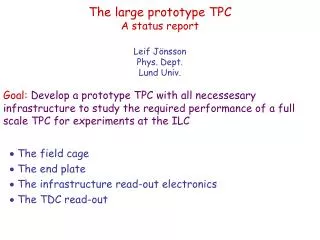
Field Cage Simulation Studyfor Prototype Cherenkov TPC Michael Phipps, Bob Azmoun, and Craig Woody
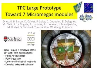
Cherenkov TPC Update • Field cage ordered • Candidate gas studies completed: • 80 Ne/10 CH4/10 CO2 • 85 Ne/10 CH4/5 CO2 • 85 Ne/5 CH4/10 CO2 • TPC chevron readout board analysis … 4 designs w/ 2 mm pitch • Fine/coarse chevrons • Fine/coarse floating strip chevrons • Field cage simulation studies … both readout modes: • TPC • Combined Cherenkov TPC • Prototype construction begins this fall at BNL
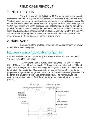
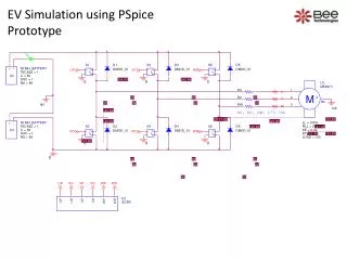
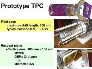
Field Cage Design • Dimensions: 144.4 x 144.4 x 115.35 mm • Strip insulation: 2 mm thick kapton foil • Strips: Mirrored layers of 26 inner/outer strips on either side of kapton • Strip details: 25 full strips of 3.9 mm length; 1 half strip of 1.9 mm length; • Strip spacing: 0.1 mm strip spacing • Removable fourth wall: to allow for two modes of testing (TPC or Cherenkov TPC) • Top bottom electrodes: Copper top plate; bottom TPC readout: mesh, triple GEM and readout board • Field Cage Simulation Geometry • Simulation software: ANSYS Multiphysics • Dimensions: Same with no mesh or GEM stack or readout components • Strips: Same. 26 mirrored inner/outer strips with kapton insulation • Strip spacing: Approximated to 0.5-1.5 mm to limit problem size • Material attributes: electrodes: ~infinite permittivity; gas: 1.0 permittivity; kapton: 3.5 permittivity • Field Cage Simulation Meshing • Finite element method Ansys simulation • Element shape: 3d tetrahedral • Nodes: 4/element • Meshing size: very fine element sides along electrode strips/spacing where there’s a lot of detail; coarse mesh in large homogenous regions (gas/top and bottom electrodes)
Preliminary proof-of-concept results • from ANSYS simulations • Note: • 2 Scenarios initially tested: • Parallel Plates (144 mm long) at distance of 110 mm • 4 field cage walls of strips (144 mm) with NO parallel plates
Parallel Plate Field Map (No Strips) Distance: ~110 mm; Length: ~144 mm 4 Sides of Strips; No Parallel Plates EF Sum ANSYS Contour Plots of Absolute Field Axes Rotated! EF Sum ROOT COLZ Plots of Percent Discrepancy Of Field Strength DIFFERENT SCALES!
Preliminary results from • ANSYS simulations of TPC field cage • Note: • Cherenkov component not included (All 4 stripped walls symmetric) • Strip spacing approximated due to simulation memory requirements • Scenario: 3 different strip spacing • 0.5 mm spacing • 1.0 mm spacing • 1.5 mm spacing
0.5 mm Strip Spacing: Scale 1 1.0 mm Strip Spacing: Scale 1 1.5 mm Strip Spacing: Scale 1 0.5 mm Strip Spacing: Scale 2 1.0 mm Strip Spacing: Scale 2 1.5 mm Strip Spacing: Scale 2
Preliminary results from ANSYS simulations of • Cherenkov TPC field cage • Note: • Geometry: 3 planes of strips w/ 1 wire plane • Wire plane: 52 wires of 0.5 mm diameter (wires in real design ~0.2 mm diameter) • Wire shape: Approximated using block volumes • Strip spacing: Approximated to 1.0 mm • Scenario tested: 4 walls of strips vs. 3 walls of strips + 1 wall of wires
TPC: Scale 1 (4 strip planes) TPC + Cherenkov: Scale 1 (3 strip planes; 1 wire plane) Wire Plane TPC + Cherenkov: Scale 2 (3 strip planes; 1 wire plane) TPC: Scale 1 (4 strip planes)