Download
1 / 25
250 likes | 373 Vues
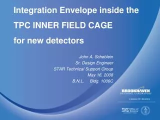
This document outlines the design and integration of new detectors within the TPC's inner field cage, as presented by John A. Scheblein Sr., a Design Engineer in the STAR Technical Support Group on May 16, 2008, at BNL, Bldg. 1006C. It details various technical drawings (SIM140, SIM181, SIM212), installation procedures, and the necessary documentation standards for the detector integration project. Accurate drawings and communications with involved institutions are emphasized to ensure proper integration and future maintenance of the STAR system.

E N D
Integration Envelope inside theTPC INNER FIELD CAGEfor new detectors John A. Scheblein Sr. Design Engineer STAR Technical Support Group May 16, 2008 B.N.L. Bldg. 1006C
Quarter Section Interface Envelope • Drawing number SIM140 Rev “J” • Shown with the SSD & SVT
Quarter Section Interface Envelopefor new detectors • Drawing number SIM140 Rev “K” • Shown without the SSD & SVT • First draft for new detectors integration • Will use the same procedure as L.B.N.L. to assign real estate
EAST SVT/SUPPORT DRAWING • Drawing number SIM181 Rev “E” • Will use this as the new detector integration drawing
EAST FTPC ENVELOPE DRAWING • Drawing number SIM212 Rev “B” • Shown with SVT • Will be used when the FTPC is replaced
SSD There are no SIM drawings of the SSD envelope
Drawing numbering system • Suggest each institution use their own numbering and revision system. • Use a 4 character prefix. (BEMC, FTPC, etc.) • Let me know what prefix you decide to use for your subsystem. • Do not want to cross reference institution drawing number to STAR drawing numbering system that was done in the past. • How many new subsystems will be added? • Please keep me in the loop during the design.
Final drawings • All drawings to be done using ANSI Y14.5 and standard drafting practices • When job is completed each institution will deliver an electronic drawing list and the model & part files to BNL Star Technical Support Group • Preferred recommended formats: • Autodesk Inventor • Autodesk Autocad • Solidworks • DXF (minimum for 2-D) • Do have Pro-Engineer #M110 (11/8/07) Have not loaded it and do not have maintenance • Must have documented files sent to STSG
Please do not install any equipment into STAR without providing documentation to the STAR Technical Support Group • Sketches • Manufacturing drawings • Solid models • Photographs • Specifications • Have the drawings reflect the parts installed.
Why do we need accurate and up to date drawings of equipment installed into STAR? Because……
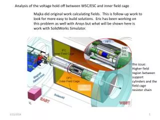
Resistor Chain……. Where is the documentation on this?
Another Resistor Chain……. Where is the documentation on this?
Resistor Chain documentation……. Where is the drawing for this resistor chain?
Questions? thank you