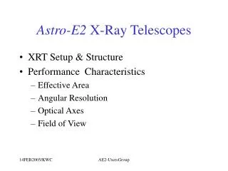
Astro-E2 X-Ray Telescopes
This document provides a comprehensive overview of the Astro-E2 X-ray Telescope (XRT) setup and structure, detailing its performance characteristics, effective area, and angular resolution. It covers the telescope's reflective optics, thermal properties, focal lengths, and orientation dependencies, as well as the optical axes and field of view. Key measurements and configurations are discussed, based on data from ISAS, highlighting the effective area at various energies and the telescope's capability to capture high-resolution images in the X-ray spectrum.

Astro-E2 X-Ray Telescopes
E N D
Presentation Transcript
Astro-E2 X-Ray Telescopes • XRT Setup & Structure • Performance Characteristics • Effective Area • Angular Resolution • Optical Axes • Field of View AE2-UsersGroup
XRT Set up • 5 XRT’s on extended bench • 4 on imagers with f=4.75m • 1 on spectrometer with f=4.50m • Same external dimension for XRT-I & XRT-S • ~ 40 cm diameter, ~25 cm height AE2-UsersGroup
Structure • Optic • Reflective optics • Grazing incidence • Conical approximation to Wolter type I • 2 reflections in 2 stages • Collimation 1 stage • Gold surface • Nested shells of segmented “cylinder” Angle of incidence (on-axis) varies from inner (smaller) to outer (larger) spectral response: Critical angle ~ 1/E AE2-UsersGroup
Geometry and Mechanics • Segmented circular elements • Reflectors positioned in slots • (Almost) all constructed out of Al • Sandwiched elements: Gold surface / epoxy adhesion layer / aluminum substrate • Thermal properties • Operational T: 20 +/- 7.5 C • Sun shields • Heating elements • Thermal Shields Quadrant construction: 4- fold symmetry in image Sandwiched structure: dependence on temperature from CTE mismatch On ground, slight resolution dependence on orientation: displacement & gravity sag AE2-UsersGroup
Basic parameters of XRT AE2-UsersGroup
XRT Characterization from ISAS Measurements • ISAS pencil beam • Full illumination Data from JAXA/ISAS Y.Maeda ISAS 30 m pencil beam AE2-UsersGroup
Full XRT Images I0 I1 I2 I3 S AE2-UsersGroup
(Configuration) U X-ray W C D Effective Area ~ 9% down from E1 ~ 4% up from E1 Full Telescope Effective Area at 4.51 keV: XRT-I: I0-I3: 340 / 334 / 331 / 335 cm2 XRT-I average 335 cm2 XRT-S: 332 cm2 AE2-UsersGroup
Effective Areas • Rough numbers, for each XRT • ~ 450 cm2 at 1.5 keV • ~ 335 cm2 at 4.5 keV • ~ 245 cm2 at 8.0 keV (smaller ~ 90% for XRT-S at higher E) • ~ 175 cm2 at 9.4 keV • Au M edge at ~ 2 keV • Efficiency slight improved (a few %) from Astro-E1 • For XRT-S, difference is mainly due to Pt Au • Especially at higher energy due to larger critical angle of Pt AE2-UsersGroup
Angular Resolution Point Spread and Encircled Energy Functions AE2-UsersGroup
Angular Resolution: HPD AE2-UsersGroup
Angular Resolution • Measured with Half-Power Diameter from Encircled Energy Function • No dependence of angular resolution on energy • Indirect energy dependence on radial position of responsible reflectors • Errors in angular resolution (axial figure errors, positioning errors, etc.) are largely radius independent • HPD ~1.8’ • Focal length errors absorbed • Sharp core: inner r ~ 0.1’: sharply rising (~ linear) EEF ; no flat PSD (c.f. ASCA mirrors) • 90% encircled power within 4’ diameter AE2-UsersGroup
Focal Lengths & Orientation Dependence • Focal Length variation • as large as 50 mm • all errors due to focal length deviation are absorbed (measurement done at nominal f) • Dependence on orientation • Hope (optimistic) that resolution will be better in space: • no displacement • no gravity sag AE2-UsersGroup
Optical Axes AE2-UsersGroup
Optical Axis • Optical axes defined as the direction of maximum output • Not the bore sites (which are well sub-arc-minutes) • Optical axes of quadrants are located within +/-1 arcmin from the nominal telescope axes • Do not contribute to angular resolution (double reflection) • Lower throughput by <~5% at 1 arc minute AE2-UsersGroup
(Configuration) U X-ray Field of View Q3 W C D F.O.V. (FWHM) (XRT-I) 0’ 45’ 90’ Al-K 12 17 36 Ti-K 12 17 32 Cu-K 9 13 26 Pt-L 8 12 22 f (arcmin.) FOV of full XRT at 4.51 keV AE2-UsersGroup
Field of View • Collimator limits stray light, but not significantly restricts the aperture • Full XRT Field of View ~ 20’ at 4.5 keV • Energy dependence via radial dependence of responsible reflectors • Smaller FOV for higher energy x-ray (smaller critical angle of reflection) AE2-UsersGroup
Parameters for the Pre-collimator AE2-UsersGroup
Satellite Alignment AE2-UsersGroup