Download
1 / 19
190 likes | 322 Vues
This document summarizes the investigations and measurements conducted from March to May 2012 regarding the optimization of bunch length and energy spread in pre-compressed bunches using RF techniques, specifically with a 325 kV electron gun. It discusses the evolution of injector setups, parameter choices based on simulations, and the development of the Free Electron Laser (FEL) setups. Key findings include insights into bunch length management, pulse stacker performance, and the impact of various parameters on injector beam quality.

E N D
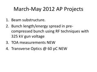
March-May 2012 AP Projects • Beam substructure. • Bunch length/energy spread in pre-compressed bunch using RF techniques with 325 kV gun voltage • TOA measurements NEW • Transverse Optics @ 60 pC NEW
These Slides • Started looking at the AP measurements done, but first got puzzled wondering how the values sol, buncher, booster etc were set • Ended up trying to go back and understand the choice of 2012 parameters, and write up the ‘story’ of this.
Summary of Machine Set-Ups in March-May • New injector set-ups for 325 kV gun field (was 230 kV for years previously) . • Only a few shifts on each project so not much set-up evolution. • Initial injector set-ups developed over a handful of shifts. • Previously (230 kV, 60 pC) had Pb ~ 500 W, BC1 phases = -20°-10°, BC2 phases are various. Despite having various ‘standard set-up files’ there was considerably tweaking shift-to-shift. • The 2012 (325 kV, 60 pC) choices of SOL and BC1 for an injector baseline evolved mainly through optimising INJ-2,3 images at Pb = 1.6 kW (#2845 was the shift where most of the parameter choices were made) • The 1.6 kW and initial guesses for SOL, BC came from prev ASTRA sims/optimisations I think. • FEL took this as the baseline then tweaked Pb, BC to get lasing (immediate change of Pb to lower values)
How did set-ups emerge? • There have been many ALICE injector simulations and optimisations using ASTRA over the years (Hywel, Chris, Bruno, …). • Including some (Julian) this year 2012 on a parameter set-up for 350 kV. • Partly based on Bruno’s 2008 simulations (and other arbitrary choices)? • These showed that the higher the buncher power the better, to reduce injector bunch length. Over 1.6 kW is desirable (this was with BC1 = -20, which was not used in the end) • Later on when BC1 = -10 was used in first shifts (#2844) a minimum bunch length at 1.5 kW was observed. • And also that the smallest injector bunch lengths are obtained with BC1 = + 20 to + 30 (yes, really +ve), for Pb = 1.0 or 1.6 kW. • Small injector bunch length = small post linac energy spread = better FEL gain. See folder \\Dlfiles03\alice\Simulations\ALICE Simulation Meeting
First Injector Setup Attempt • First inj set-up with 325 kV (#2840, 14 Mar) • Chose SOL-01 at 4.0 A by observing INJ-1 while scanning SOL from 4.0 A to 4.4 A • 3.9 A = 330 Gauss is the optimum for (350 kV, 80 pC) according to BDM ASTRA sims of EPAC 08. • Then Pb = 1.5 kW, BC phases = -10/+15, SOL-02 = 2.6 A (220 G) • Not sure what the reasoning behind these parameters was. #2840 LOG
Pulse Stacker Studies • Pulse stacker was tried in and out on #2844 • Used params BC = -10/+15 • Bunch length measured w/wo pulse stacker (RF zero cross quick and dirty, #2844) clear minimum at Pb ~ 1500 W • Stability on INJ-5 seemed better WITH pulse stacker.
‘Final’ Baseline Injector Set-Up in March 2012 • Over #2845, YMS tired various SOL-01,02, BC1 BC2 phases. All with Pb = 1.6 kW. • Main critera was to get beam looking ‘nice’ on INJ-2, INJ-3 • BC1 varied from -20 to -10. • Final set up Pb = 1.6 kW, BC = -15/+22 SOL-01,02 = 4.0, 2.8 was one that gave the nicest images. • Conclusion that only BC1 grad and phase affects the INJ-2,3 beamsize. • And, final decision on pulse stacker, INJ-2,3 not much better without p.s., so leave it in.
FEL setups development • FEL first lasing #2865: 325 kV, 60 pC, Pb = 1.25 kW, BC1 phases = -14/+12, LC phases = +14/+14. • later on same shift more FEL power was achieved with BC1 = -12 (and other changes) • First lasing shift #2865 carried on from #2864, which used a starting point with Pb 1.5-1.6 kW, BC1=-15°, from #2845 ‘final injector set-up’ • FEL lasing tweaking involves tweaking Pb, BC1, BC2 pragmatically from the starting point until achieving lasing • Buncher power reduced significantly 1.61.25 in these tweaks. • BC2 phase moved closer to crest to chirp bunch positively – cause bunch compression in FEL. • The snapshot on #2865 looks very different on INJ2-3 to the starting baseline found in #2845. • Raises the question whether INJ-2,3 are the best thing to optimise on, and if not, what is?
Conclusions (set-ups) • Perhaps the injector param space has not been explored as thoroughly as it might have been. • Particularly Pb value was not explored very thoroughly in dedicated injector set-up shifts. • What is the value of more dedicated injector set-up work?
Bunch Length/Energy Spread in Pre-compressed Bunch • Several observations in set-up period and AP shifts • Bunch charge questions (scope “probe gain” problem, and differences between how people define the bunch charge – first bunches, rest of train etc)
Pre-Compressed Bunch Length – General Features • Absolute bunch length of ~1.8-2.5 mm FWHM measured at booster exit (#2867,#2869) for • Pb = 1.6 kW, BC1 = -15 • Period 12 (2011) bunch length was ~ 1.0-2.6 mm* for THz-like set-ups • At linac exit, bunch length measured at 2.0 -3.0 mm FWHM over a variety of conditions • Period 12 generally measured much smaller post-linac bunch lengths 1mm FWHM • Quick and dirty booster exit bunch length vsPb, with BC1 = -10 gives minimum at Pb = 1.5 kW • Does this agree with simulation? • Bunch length evolution in INJ line (conflicting observations) • One shift #2867 measured post-booster AND post-linac bunch length indicating bunch lengthening in INJ (Pb = 1. 6 kW, BC = -15/+22). • Another two shifts (#2847,#2852) recorded a contradictory observation – bunch shortening • The AR1-1 energy spread for BC2 at +22 and +30 was measured with the equivalent linac offcrest phase and found dE greater at BC2 = +30 than at BC2 = +22 • At BC = +30, linac crest phase same as phase min AR1-1 energy spread bunch not chirped at linac entrance. Thus at BC=+22, positive chirp, head > tail. And at BC+22 the post linac energy is smaller, so … • … this implies bunch shortening in injector at BC = +22 (R56) *Corrected for incorrect INJ-YAG-05 calibration
Energy Spread Observations • #2841. Uncorrelated energy spread in injector at 5 keV RMS (~0.1%) over large range of Pb (0.5-1.5 kW), BC1 (-20,+10) params. About 10 pixels on INJ-YAG-05 • In 230 kV days we did observe ~ 5 KeV RMS energy spread (40 pC) when measuring uncorrelated energy spread vsPb (2010 FEL commissioning days), but not over whole. • In 2011 with 60 pC running uncorrelated energy spread not studied in detail May 2010
#2867 Bunch Length Evolution • AW/PW #2867 did some bunch length evolution studies and analysis • \\Dlfiles03\Apsv4\Astec\Projects\ALICE\ALICE_Physics_Meeting\2012_04_10 • Some agreement between measurements (bunch lengthening) and prediction, based on R56 of injector set-up and estimated post-booster chirp of bunch • But +vs/-ve signs are critical to understand if this should be bunching or debunching • R56 #2867, 19:11 apply BURT: 1120318-125755. R56 is the OPPOSITE SIGN to post linac compression, And in the injector we assume head is higher energy than tail This should lead to bunching not debunching. But can we trust the ELEGANT R56 plot, or should we try and measure R56 in the injector? ELEGANT R56 using BURT: 1120318-125755 I notice that increasing INJ-Q5 strength by 50% REVERSES THE SIGN of R56. Checked that Q-05 is not model is not central as in real life.
Two Beam Studies Relevant • In March-May 2012 230 kV revisted for two beam studies • Two beam z-separation as function of Pb, compared with ASTRA sims of RMS bunch length vs Pb (BC1 = -10, 60 pC) • Both measurement and sims show minimum bunch length/separation at the same value Pb = 1 kW
Conclusions (longit. measurements) • Interesting that post-linac bunch lengths seem longer with the 325 kV set-ups • Some conflicting data on longit. evolution in injector • Is it worth pursuing this further with lots of shift work? • Fiddly measurements, might get - as in the past experience (2011) - a large amount of somewhat inconclusive data • Many difficulties in getting precise measurements with current injector diagnositcs (beta minimisation, large energy spread ‘reconstruction’, difficulty in knowing the bunch charge in first bunches …)
TOA First Attempt # 2907 19 April 2012 • Prelim results presented at • \\Dlfiles03\Apsv4\Astec\Projects\ALICE\ALICE_Physics_Meeting\2012_05_01 • R56 measured by TOF at AR2-BPM-01 and ST1-BPM-01. • First measurement of post linac R56 at AR2-BPM3 (#2907) gave 150 mm, expect 280 mm naively • And ELEGANT model of BURT 1120416_2351 on this shift predicts R56 = 450 mm • ARC is NOT isochronous for this BURT. AR1-Q1-4 are not the right values for isochronicity, and R56 is VERY sensitive to these quads. • Another reason for discrepancy could be because AR1-SEXT-01 was on (2.8 A), misalignment could affect R56 • Dipoles are not perfect symmetrical currents. On this shift in comp-chicane first 3 dipoles are symmetric and fourth one is 2 % weaker. AR2-Dipoles differ by < 0.5%. ELEGANT investigations suggest this alone isn’t enough to explain the discrepancy. • R51, R52?? • Also attempted measurement of injector R56 but inconclusive. Try again in future. Change in TOF (mm) vs fract change in beam energy ELEGANT BURT 1120416_2351 post linac R56, AR1-SEXT-01 off
#2908 (Deepa, Julian) • TOF @ AR2-BPM-01 vs AR1 params (Q1/3, Q2/3, SEXT-01, SEXT-02) • Indicates very strong effect from AR1-Q1,Q4, as expected. • Trend of R56 Nominal Q1,4 setting, first measurement was 150 mm (with AR1-SEXT-01 on), here it is 191 mm with AR1-SEXT-01 off AR1-SEXT-01/2 = 0 A AR1-SEXT-01/2 = 0 A Q2,3 nominal value AR1-SEXT-02 = 0 A Shouldn’t this be the same value as this? AR1-SEXT-01 = 2 A for first point, = 0 A for other two points Repeatability of measurements? Shouldn’t this be the same value as #2907, 150 mm?
#2927 FJ/HA/Terry Atkinson Repeatability of Measurment Wanted to get a more detailed scan of R56 vs Sext-01 to see trend. Scanned AR1-SEXT-01 0 A to 9 A then back to repeat a point at 3 A BPM No particular trend observable but alignment of beam w.r.t quadrupole unknown R56 Pretty repeatable AR1-SEXT-01 (A)
#2996, 2998 03 July 2012 • Aim was combined effect of AR1 steering and AR1-SEXT-01 on R56. • Attempt to use AR1-BPMs to judge trajectory. • AR1-BPMs have new EMMA-style single bunch electronics. • Also attempt beam-based calibration of AR1-BPMs