Download
1 / 77
780 likes | 1.22k Vues
Quiz 1 Review Op Amps (Continued). Notes. Test is TOMORROW 6:00 p.m.-8:00 p.m. DCC 308 If you’ve just started Project 1 you are a week behind ! (Get to open shop this weekend) Make sure to find the studio attendance sheet if it doesn’t make it around to you. Review Topics.

E N D
Notes • Test is TOMORROW 6:00 p.m.-8:00 p.m. DCC 308 • If you’ve just started Project 1 you are a week behind! (Get to open shop this weekend) • Make sure to find the studio attendance sheet if it doesn’t make it around to you
Transfer Functions and Phasors • Apply the voltage divider equation and parallel and series combination rules to find transfer functions using complex impedance expressions • Simplify the transfer function to find a function which governs behavior at low and high frequencies. • Find an expression (or value) for the magnitude and phase of the simplified transfer function at the corner or resonant frequency • Find Vout or Vin from the transfer function (magnitude and phase)
Transfer Functions and Phasors • Find the transfer function for the above circuit. • Write in terms of Z impedance first
Transfer Functions and Phasors Z Z Z • Transfer function for the above circuit. • a) Combine Impedances: Find ZR2C1 • b) Use voltage divider to find H=Vout/V1 • c) Substitute component values • d) Simplify
Transfer Functions and Phasors 2) Assume R1=R2=1KΩ and C1=1μF, evaluate the magnitude of the transfer function at ω=0 and ω=∞. • Magnitude of the transfer function at ω=0 • For low frequencies, the lowest power dominates
Transfer Functions and Phasors 2) Assume R1=R2=1KΩ and C1=1μF, evaluate the magnitude of the transfer function at ω=0 and ω=∞. • b) Magnitude of the transfer function at ω= ∞ • For high frequencies, the highest power dominates
Transfer Functions and Phasors 3) See crib sheet When doing analysis ωt will eventually drop out so just θ is used
Transfer Functions and Phasors Need both Magnitude and Phase from the transfer function. Magnitude
Transfer Functions and Phasors Need both Magnitude and Phase from the transfer function. Phase
Transfer Functions and Phasors Using Transfer Functions (on crib sheet!) In the form
Filters • Understand how capacitors and inductors work at very low and high frequencies • Redraw a given RL, RC or RLC circuit at low and/or high frequencies and identify low pass, high pass, band pass and band reject filters • Find resonant frequency of RLC circuits • Find corner frequency of RC and RL circuits • Identify whether a signal of a certain frequency be passed rejected or something in between by a filter
Filters • Let Rs=0Ω Redraw the circuit above for very low frequencies • What is Va and Vb at very low frequencies?
Filters 2) Va=0V, Vb=0V
Filters • Let Rs=0Ω Redraw the circuit above for very high frequencies • What is Va at very high frequencies?
Filters 2) Va=8V If Va is considered the output, what type of filter is this?
In Class Problem: Filters: Resonant Frequency • Redraw this circuit at low frequencies • Redraw this circuit at high frequencies • What type of filter is this? • If L1=2mH, L2=2mH, C1=0.5uF and R13K, what is the resonant frequency in Hertz?
In Class Answer: Filters: Resonant Frequency Low Frequencies Inductors: short Capacitor: open Vout=0V High Frequencies Inductors: open Capacitor: short Vout=V1 High Pass Filter
Transformers and Inductors • How to apply transformer equations • Basic characteristics of transformers • Calculate unknown inductance given the capacitance or visa versa • Calculate resonant frequency given inductance or capacitance or visa versa • Estimate inductance of a coil given some dimensions
Transformers (Homework 3, #9) You are given the transformer pictured below. What is the voltage across the load resistor if “a” is 9, R2 is 5K ohms, R1 is 3K ohms, and V1 is 62 Volts? Note that R1 is large so you CANNOT assume that it has negligible resistance. Give your answer in volts.
Transformers (Homework 3, #9) You are given the transformer pictured below. What is the voltage across the load resistor if “a” is 9, R2 is 5K ohms, R1 is 3K ohms, and V1 is 62 Volts? Note that R1 is large so you CANNOT assume that it has negligible resistance. Give your answer in volts.
Transformers (Homework 3, #9) • Find Zin • Use the voltage divider to find Vs (due to non-negligible voltage drop across R1 • Use ratio relationship below
Circuit Analysis • Handle combinations of parallel and/or series resistors • Give resistance expressions in equation form, rather than as a number. • Find voltages or currents through any resistor • Find the total resistance or current • Know the voltage divider equation • Find the voltage across a resistor in a voltage divider configuration.
Circuit Analysis • Find the total resistance of the circuit, seen from the voltage source • Write equation first then put in the numbers! • Given V1=5V, R1=2000Ω, R2=3000Ω, R3=200Ω, R4=800Ω
Circuit Analysis • Find the voltage across R1 • Find the current through R3 • Given V1=5V, R1=2000Ω, R2=3000Ω, R3=200Ω, R4=800Ω
PSpice Instrumentation and Components • Know which trace corresponds to which voltage point on a simple circuit • Describe specific steps you’d follow to obtain a certain output for AC sweep, DC sweep or Transient Analysis • Understand how to set parameters for function generator • Understand how to use the oscilloscope
Op-Amp Circuits: Quick Review • Op-Amps are most commonly used to ________ a signal. • Inputs to the op-amp are called the _______ and _______ inputs. • Unpredictable high gain that is multiplied by the input signal is called ____-____ ____ or ______ ______. • Extreme gain causes __________. • What day, time, and location is Quiz 1?
Op-Amp Circuits use Negative Feedback • A balancing act between gain and negative feedback for a stable circuit How do you “design” negative feedback in the circuit?
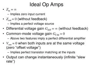
Op-Amp Analysis • We assume we have an ideal op-amp: • infinite input impedance (no current at inputs) • zero output impedance (no internal voltage losses) • infinite intrinsic gain • instantaneous time response
The Inverting Amplifier Is this the same as intrinsic gain?
Inverting Amplifier Analysis • Step 0: Understand the Golden Rules! • Rule 1: VA = VB (feedback network brings the input differential to zero) • Rule 2: IA = IB = 0 (inputs draw no current)
Inverting Amplifier Analysis inverting input (-): non-inverting input (+): Step 1:Re-draw the circuit Remove the op-amp from the circuit and draw two circuits (one for the + and one for the – input terminals of the op amp).
Inverting Amplifier Analysis Step 2:Write equations for the two circuits inverting input (-): non-inverting input (+): inverting input (-): non-inverting input (+): VA=0
Inverting Amplifier Analysis Step 3:Simplify using Golden Rules and solve for Vout/Vin VA=VB=0 therefore Golden Rule! What is this saying about how you can design your gain?
PSpice Inverting Amplifier Use the uA741 op amp to model your circuits Can’t find it? It is in the EVAL library Add library “Eval” Input amplitude: 200mV Rf=10k Ω Rin=1k Ω What should the simulated output look like?
Non-inverting Amplifier Analysis inverting input (-): non-inverting input (+): Step 1:Re-draw the circuit Remove the op-amp from the circuit and draw two circuits (one for the + and one for the – input terminals of the op amp).
Non-inverting Amplifier Analysis Step 2:Write equations for the two circuits inverting input (-): non-inverting input (+): Voltage Divider inverting input (-): VA=Vin non-inverting input (+):