Download
1 / 49
540 likes | 777 Vues
Introduction to Environmental Analysis Environ 239 Instructor: Prof. W. S. Currie GSIs: Nate Bosch, Michele Tobias Skills Unit 1: Learning to use a Geographic Information System (GIS). Components of a GIS or GIS analysis. Spatial maps of features. Database of feature attributes.

E N D
Introduction to Environmental AnalysisEnviron 239Instructor: Prof. W. S. CurrieGSIs: Nate Bosch, Michele TobiasSkills Unit 1:Learning to use a Geographic Information System (GIS)
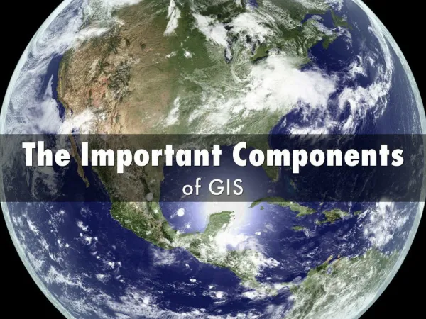
Components of a GIS or GIS analysis Spatial maps of features Database of feature attributes Statistical and modeling analyses The historical foundation and organizing principle in GIS is the map
Data layers in a GIS A GIS stores pieces of information, i.e. data (values of a variable), in which each piece of information has a spatial location For one variable, across the extent, this is called a data layer A data layer is also called: • A ‘theme’ • A ‘grid’ • (if raster format) • An ‘image’
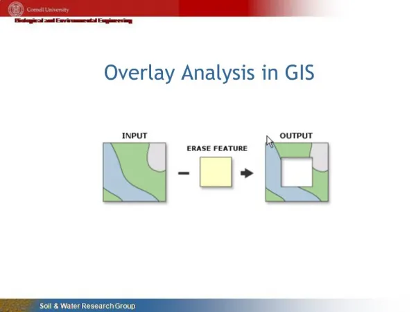
Data layers or themes Themes can be overlaid if they are attached or registered to a common spatial reference system
Maps, data layers, process:Example of an analysis of potential soil erosion Lillesand & Kiefer 2000, Remote Sensing & Image Interpretation
Example: GIS analysis of potential soil erosion Soil erodibility Land cover slope
Types of geographic features in a data layer or theme Points (0 dimensional) Lines (1 dimensional Areas (2 dimensional) Mitchell, 1999, The ESRI Guide to GIS Analysis, Vol I
Features in a map layer or theme • Point • Residence, or business location • Sampling point in a field study • Line • Township or county lines • Shoreline of a lake • Centerline of a river or stream • Contour line on a topographic map • Street centerlines • Area • Census block • Soil type • Vegetation community type • Lake surface
Raster vs vector data formats Original line map Raster Vector In a GIS, spatial delineation of features must be stored as either raster, or vector format Lillesand & Kiefer 2000, Remote Sensing and Image Interpretation
Polygons approximate areas area polygon
Polygon information stored as a set of (x, y) coordinates polygon x4, y4 x1, y1 x2, y2 x3, y3
Raster versus Vector representation of types of features Johnston 1998, Geographic Information Systems in Ecology
Paper maps Vector format Aerial photography Digital remote sensing – e.g. Landsat, NOAA satellites Raster format Computer models of spatial processes Reason for 2 different formats for GIS data
USDA County soil mapDane County, WI Example of a map that would be converted easily to a vector format
2020 total annual NOy Deposition (mMole m-2 yr-1) From Galloway et al. 1994 (Ambio)
Types of features in a data layer or theme Points, lines, areas: This is vector format in ArcView Note that points and lines can be given symbol width for display, but they are still zero-dimensional (points) and one-dimensional (lines) vector objects Mitchell, 1999, The ESRI Guide to GIS Analysis, Vol I
Conversion of data from raster to vector Raster Vector lines Rasters, or grid cells polygons
Converting from vector to raster format:two methods “largest share” rule Vector Raster Raster “central point” rule
Converting between raster – vector formats: does it cause loss of information? • Vectorization of raster data: typically no new loss of information • Rasterization vector data: potential new loss of information. Considerations: • Method used to convert • Scale, or grid resolution, used in the conversion
Graded question on assigned reading • See Skills Unit web page
ArcView Hierarchy of terms • Project • contains potentially many views • View • contains potentially many themes • Displayed one on top of the other, in the order shown in the ‘table of contents’ of the view • Themes • A theme is a single “data layer” • (Each theme contains many features) • Features • Polygons, roads, streams, county lines, etc. • (Features: think point, line, or area) • Fields • Each feature has a line in an attribute table, with each column of attributes called a field
A “Theme” in ArcView • A Theme is a single ‘data layer’ • “A Theme represents a distinct set of geographic features from a particular geographic data source.” • Examples: • A map of street center lines • A map of county delineation lines • A map of land use / land cover • A map of soil types • A collection of Themes composes a View. • Themes are listed in the Table of Contents of the View.
A “View” • A View is specific to the ArcView Project. • “A view is an interactive map that lets you display, explore, query and analyze geographic data.” • A View is a collection of themes. • A View does not contain the spatial data, instead it references the data. Multiple Views can reference the same data. • Each View has a Table of Contents at the left. This contains themes. You click on the views that you want displayed; the topmost ones are drawn last.
Skills Unit 1:Learning to use a Geographic Information System (GIS) Second lecture
Georeferencing(or geolocation, geocoding) Ways to organize spatial locations of objects or areas (fields) on the Earth’s surface Three main categories we will consider: • “Miscellaneous” • Street addresses, zip codes, and others • Geographic • Latitude, longitude • Projected • 2-d maps and 2-d computerized data layers
Features that a georeferencing system needs to have • Spatial locations that are unique • Able to be communicated easily and unambiguously, hopefully worldwide • Relatively unchanging through time
Miscellaneous types of Georeferencing • Street addresses Shortcomings: • Town names are not unique • Addresses are not always spatially sequential • Linear referencing • E.g. distance from an intersection. Shortcomings: • Roads not always straight; road names not always unique; road names change • Zip codes • Widely used in some types of GIS analysis • Do not allow distance or area calculations • PLSS (Public Land Survey System)
USPLS (or PLSS)U.S. Public Land Survey System • Also called “Land Ordinance of 1785” • Also called “Township and Range” system • Dominant system for land surveying in western US (west of Ohio) • “Federal System of Rectangular Surveys” • North-South Principal Meridian surveyed • East-West Baseline surveyed • Squares 6 miles x 6 miles (called townships) laid out on each side of meridian Illustrate on overheads
USPLS (or PLSS)U.S. Public Land Survey System • 1 mile x 1 mile sections (36 per township) laid out within each township • Back-and-forth numbering, in rows, numbers 1 – 36 • Each section divided into four quarter-sections • Each quarter-section was 160 acres, the size of a typical family farm in the mid-late 19th century Illustrate on overheads
USPLS (or PLSS) Public Land Survey System • Problem: Earth is not flat! • You cannot tile a sphere with perfect squares • All squares were not exactly 6 miles, and rows need to be offset from one another slightly
Shortcomings of all of these miscellaneous means of geolocation • Not systematic, or standardized worldwide • Can not, in a standardized and precise manner, calculate distances or areas based on these geolocational representations
“Geographic” system Latitude, longitude • Defined as angles relative to the center of mass of the Earth, and the north-south pole axis • Longitudes are slices that are parallel to the Earth’s axis; each longitude “line” is a half-plane that is at angle with respect to the Prime Meridian in Greenwich, England • Latitudes are angles with the Earth’s axis; with zero defined as perpendicular to the axis and passing through the equator
Shortcomings of latitude-longitude (“geographic” system) • Lat-lon created for a sphere, but the foundations of mapping and GIS are 2-dimensional maps or data layers • Cannot calculate areas or distances easily from lat-lon values Take great care if you use lat-lon coordinates as Cartesian coordinates on a plane: • Shapes in lat-lon system are very different from shapes on the earth’s surface, esp. at high latitudes (a circle on the Cartesian plane would be a squashed ellipse on the Earth’s surface)
Georeferencing(or geolocation, geocoding) Ways to organize spatial locations of objects or areas (fields) on the Earth’s surface Three main categories we will consider: • “Miscellaneous” • Street addresses, zip codes, and others • Geographic • Latitude, longitude • Projected • 2-d maps and 2-d computerized data layers
Map Projections • GIS historically developed from mapping and analysis in 2-dimensional planes • Planes representing portions of the Earth’s surface • Projections convert geographic coordinates (latitude-longitude on a sphere or ellipsoid), to a planar system • All projections result in some distortion • Distortion is least at the point(s) of contact of the plane and curved surfaces • Distortion grows larger with distance from these point(s) of contact • Tangent vs secant • Secant minimizes distortion by allowing 2 points of contact Illustrate on overheads
Three different projections • UTM (Universal Transverse Mercator) • Worldwide standard; 60 different projections, each a zone 6 longitude degrees wide, in a common framework. • State Plane Coordinates • Each US state has its own. The Michigan State Plane system has three zones, which is a shortcoming for any GIS work that has to cross the zone boundaries. • Michigan Georef • Has benefits over the state plane system for Michigan: The main benefit is that there is only one zone • Our GIS labs will all take place in Michigan Georef projection
State Plane Coordinates (SPC) • A nationwide system in the U.S, with maximum locational error of 1 in 10,000 • Like UTM, SPC is a projected system • SPC has less error than UTM: UTM is accurate to 1 in 2,500 • To achieve this, the U.S. was divided into 125 zones • Along state boundaries • Large states have more than one zone • Within states with more than 1 zone, along county boundaries • A separate projection in each zone • Minimizes projection distortion within each zone • Used by state and local governments (dept. of natural resources, transportation, zoning, etc.) • Michigan state-plane system has 3 zones
Michigan Georef • Central axis is skewed NW-SE across upper and lower peninsulas of MI • Less precise than MI State Plane, but Georef has one zone • Units are in meters, which allows calculations of distances and areas • Many data layers (“themes”) are available (free!) from the Michigan Geographic Data Library web site • http://www.mcgi.state.mi.us/mgdl/
Converting among Georeferencing systems • Conversions are needed. Some applications need to convert . . . • Addresses, zip codes, etc. into UTM or State Plane for spatial analysis • UTM or State Plane or Georef coordinates into zip codes or townships • One State Plane or UTM system into another, for combining disparate spatial datasets • Conversions exist • Some built into GIS software • Others easily available (MGDL web site has conversions to & from Michigan Georef)
Datum • To specify a projection, you need to know the type of projection and the Datum • The Datum is the mathematical model of the Earth as an ellipsoid, used to make the projection from the lat-lon to the projected system • The datum is also needed to calculate three-dimensional coordinates near the Earth’s surface (elevation) Illustrate on overheads
Datum • Current international standard: WGS84 • World Geodetic System 1984 • Current US standard: NAD83 • North American Datum 1983 • Virtually identical with WGS84 • Michigan Georef uses NAD83 • Still in use in US: NAD27 • From 1927