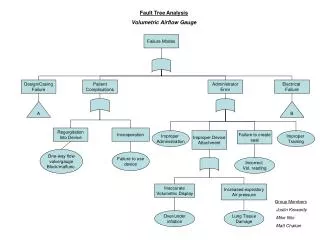
Fault Tree Analysis
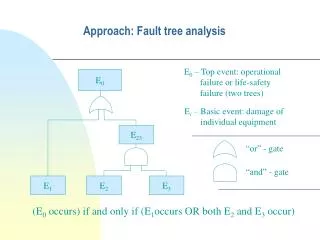
Fault Tree Analysis. Part 5: Digraph-Based Fault Tree Synthesis Procedure (Multiple Loops). HEAT EXCHANGER WITH MULTIPLE FEEDBACK LOOPS. V 1. 10. 1. 2. A. O. 3. 4. HOT. T. 9. 5. 6. SET PT. TRC. V 2. A.C. AIR SUPPLY. 8. COLD. 7. T3. T3.

Fault Tree Analysis
E N D
Presentation Transcript
Fault Tree Analysis Part 5: Digraph-Based Fault Tree Synthesis Procedure (Multiple Loops)
HEAT EXCHANGER WITH MULTIPLE FEEDBACK LOOPS V 1 10 1 2 A. O. 3 4 HOT T 9 5 6 SET PT. TRC V 2 A.C. AIR SUPPLY 8 COLD 7
T3 T3
MULTIPLE FEEDBACK LOOP OPERATOR IF the Output Variable Is On Two NFBLs of Equal Power and Speed Output (Value) OR Large or Fast Disturbances Off both Loops Loops Pass Disturbances A AND Disturbances Inactive Loops OR OR Inact Both Inputs (Value) (Off both NFBLs) Loop I Causes Loop II Normal Loop I Normal Loop II Causes AND AND AND OR OR EOR Loop II OK (prob = 1) Loop I OK (prob = 1) EOR Inact Loop I Inact Loop II Loop I Causes Loop II Causes
A OR BOTH CAUSE Loop I Cause Loop II Inact. Loop I Inact. Loop II Cause AND AND AND EOR EOR EOR OR EOR OR Loop I Causes Loop II Causes Loop I Causes Inact. Loop II Loop II Causes Inact. Loop I
(page 1) T4(+1) OR -1 T3(+1) OR -2 2 NFBL OR -3 OR -4 (page 3) Fire at Hx(+10) T2(+10) T9(+10) AND -16 (page 2) OR -15 OR -14 T1(+10) T8(+10)
(page 2) AND -16 OR -17 OR -18 Fire at Hx (+1) T2(+1) T9(+1) -6 Loop I cause -7 Loop II cause OR -21 OR -20 AND -19 (page 3) (page 3) T1(+1) T8(+1) -9 Loop I Inactive -11 Loop II inactive (page 3) (page 3)
(page 3) OR -4 AND -8 AND -5 AND -10 -7 EOR -7 EOR -6 OR -9 -6 OR -11 M9(-1) (page B) M2(+1) (page A) OR -12 OR -13 V1 stuck TRC stuck TRC on manual Sensor stuck TRC stuck V2 stuck TRC on manual Sensor stuck
(page A) -22 OR 1 NFBL -23 -24 OR EOR -25 AND Falls Open (+1) Reversed -26 OR -12 1 NFBL -27 OR -30 -28 -29 OR AND EOR OR -31 Set Point (+1) Air Press. (+10) TRC Falls High (+1) Air Press. (+1) TRC Reversed (page C) TRC Stuck TRC On Manual Sensor Stuck
(page B) -36 OR 1 NFBL -37 -38 -40 OR AND EOR -39 OR -13 (page 3) (-10) Falls Closed (+1) Reversed (-1) -41 OR 1 NFBL -42 -43 -45 OR AND EOR -44 OR Set Point (+1) Air Press. (+10) TRC Falls High (+10) Air Press. (+1) TRC Reversed -32 TRC Stuck TRC On Manual Sensor Stuck (page C)
(page C) P5(-1) -32 2 NFBL OR -33 -34 -35 OR AND EOR No reverse gain T3(-1) Temp. Sensor Fails Low (+1)
[Example] TANK PRESSURIZATION PROBLEM This process separates a two-phase stream (stream 1) into vapor (stream 2) and liquid (stream 3) using a flash tank. Level in the tank is controlled by a negative feedback loop through a level controller. A pressure sensor monitors the tank pressure which is relayed back to the control room. Should the operator see a high pressure on the indicator, he is instructed to manually open valve V1 which drains the tank and reduces the pressure. The relief valve is designed to vent the vapor portion of the tank mixture when high tank pressure is encountered.
7 RV 1 2 P 5 L LC 4 V1 3 6 A.O.
TOP EVENT: • Normal Conditions: • Flow in stream 1, 2, and 3. Tank 50% full. Level controller on automatic. Relief valve and V1closed. • Equipment Behavior: • Level Sensor : P5 increases when level increases. The sensor has stuck during operation. • Level Controller: P4 increases when P5 increases. The controller set point may be changed. The controller may be switched to manual operation. • Control Valve : Increasing P4 causes the valve to open. • Valve V1: The valve is manually operated. It may stick. • Relief Valve : The valve may fail shut. If the relief valve is full of liquid, it will not vent the system fast enough.
PLUG IN LINE 2 +10 0 ( RV FAILS CLOSED) +1 +1 LOOP II +1 RVP OPERATOR ACTION -1 0 ( L = +10) 0 (PRESSURE SENSOR) INOPERATIVE 0 +1 (OPERATOR DOES NOT SEE PRESSURE INDICATOR) 0 (OPERATOR OPENS WRONG VALVE) 0 (V1 STUCK) +1 +1 L +1 LOOP I 0 -10 V1P (LEVEL SENSOR STUCK) +1 0 LEVEL SET POINT -1 -1 (CONTROLLER ON MANUAL) LOOP III +1 +1
(page 1) OR 2 NFBL ( Loops Cause ) (Loops Pass Disturbance) AND No Uncontrollable Disturbances! OR (See Page 2) OR OR Plug In Line 2 AND L (+10) RVP (-10) Loop II inactive OR L (0) OR (See Page 2 ***) Loop I inactive * Loop I cause OR RV Falls Closed L (+10) RVP (0) Loop II cause VIP (0) ** OR inconsistent V1 Stuck Operator Action (0) Operator Opens Wrong Valve OR Pressure Sensor Inoperative Operator does not See Pressure Indicator
(page 2) ( Loops Cause ) OR AND AND AND L (+10) OR L (0) RVP (-10) RVP (-10) L (+10) ( Done ) *** ( Done )*** ( Done ) * L (+10) RVP (0) RV Falls Closed Both cause *** 1 NFBL OR ( See Page 1 ) Loop I inactive Loop II cause AND OR VIP (0) ( Done )** OR ( See Page 1 ) Loop I cause Loop II inactive Isolation valve Closed in error OR Level Set Pt. (+10) L (-10)