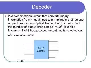
High-Speed Analog Min-Sum Iterative Decoder Design for (32,8) LDPC Codes
This paper presents a detailed exploration of a high-speed analog min-sum iterative decoder designed for a (32,8) low-density parity-check (LDPC) code. The authors discuss the advantages of their approach over traditional methods, such as lower power consumption, faster speed, and improved decoding performance. The min-sum decoding algorithm is outlined, including the basic modules and circuits utilized. Measurement results from a fabricated chip demonstrate its effectiveness, particularly in low-SNR conditions, showcasing its potential for use in advanced CMOS technologies.

High-Speed Analog Min-Sum Iterative Decoder Design for (32,8) LDPC Codes
E N D
Presentation Transcript
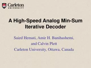
A High-Speed Analog Min-Sum Iterative Decoder Saied Hemati, Amir H. Banihashemi, and Calvin Plett Carleton University, Ottawa, Canada
Outline • Introduction • Min-Sum Decoding Algorithm • Basic Modules and Circuits • Analog Min-Sum Decoder for a (32,8) Code • Measurement Results • Conclusion
Introduction • Why analog? • Lower power/speed ratio • Lower noise generation • Lower area consumption • Better decoding performance (Hemati and Banihashemi, 2003) Previous Work: - Loeliger et al., 2001 - Mondragon-Torres et al., 2003 - Gaudet et al., 2003 - Morez et al., 2000 - Hemati et al., 2003 - Winstead et al., 2004 - Amat et al., 2004
Other Approaches: - are based on belief propagation (BP) - have a differential multiplier as the basic processing module - use the well-known Gilbert differential multiplier • Linearity of the Gilbert multiplier relies on the exponential behavior of bipolar (or quasi-bipolar weakly inverted CMOS) transistors. • Bipolar technology is expensive and weakly inverted CMOS transistors are slow. • Multiple-input modules are constructed by cascading two-input Gilbert multiplier modules.
Our Approach: - is based on min-sum (MS) - does not require an estimate of the noise power - is more robust against quantization noise - is based on current mirrors - multiple-input modules can be directly implemented • There are simple modifications of MS that can perform very close to BP.
Min-sum Decoding Algorithm Basic operations in MS: mv V C
Basic Modules and Circuits Current buffers duplicate input current at the output with flipped sign
Basic modules and circuits Variable Nodes
Basic Modules and Circuits Check Nodes
Basic Modules and Circuits An RTAS module, (a) current rectifier, (b) sign extractor
Basic Modules and Circuits (b) (a) (a) A current-mirror, (b) a current-mode 3-input max WTA.
Basic Modules and Circuits ASTR module
Analog MS Decoder for a (32,8) Code Tanner graph of the code
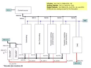
Analog MS Decoder for a (32,8) Code Architecture of the implemented chip
Analog MS Decoder for a (32,8) Code Microphotograph of the fabricated chip
Conclusion • A modular methodology was proposed for designing CMOS analog MS iterative decoders. • The modules are based on current mirrors and therefore our approach can be used for implementing analog MS decoders in advanced bipolar and CMOS technologies. • A proof-of-concept analog MS decoder chip for a (32,8) regular LDPC code was fabricated and tested. • In low-SNR region, measurement results are close to the simulation results based on SR-MS algorithm.