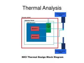
Testing and Failure Analysis Thermal Analysis (TA)
Testing and Failure Analysis Thermal Analysis (TA). Professor Joe Greene CSU, CHICO. Topics. Testing Electrical Physical Mechanical Thermal Failure Analysis Stress Differential Scanning Calorimeter Glass Content. Testing. Electrical Testing

Testing and Failure Analysis Thermal Analysis (TA)
E N D
Presentation Transcript
Testing and Failure AnalysisThermal Analysis (TA) Professor Joe Greene CSU, CHICO
Topics • Testing • Electrical • Physical • Mechanical • Thermal • Failure Analysis • Stress • Differential Scanning Calorimeter • Glass Content
Testing • Electrical Testing • Plastics are good insulators, handles for screw divers etc. • Ability to withstand exposure to electrical current. • Conditioning samples • ASTM D-618: 73F (23C) and RH of 50% for > 40 hours • Dry samples to get consistent results • Dielectric Strength • Amount of voltage required to arc through a specimen of plastic (figure 10-1) • Voltage starting at 0 Volts is applied to one side of specimen and increased until it arcs through.
Testing • Dielectric Constant • The electrical capacitance of a specific plastic cross section as a ratio to that of a similar cross section of air. • Volume Resistivity • Ability of a plastic to resist an electric current through its bulk. (Fig 10-3) Used for electrical insulators. • Surface Resistivity • Ability of a plastic to resist current across its surface. (Fig 10-5) • Arc Resistance • Amount of time required for an electrical arc to carbonize the surface of a specimen. (Fig 10-5)
Physical Testing • Shrinkage Rate (ASTM D-955) • Test is used to measure the amount of shrinkage that occurs in a plastic after it has been heated and injected into a mold, then allowed to cool. (Figure 10-6) • Dimensions are measured in two dimensions from marks in tool or dimensions of mold hot and of part. • Plastic parts can shrink much as 20 percent by volume, when measured at the processing temperature and the ambient temperature. • Crystalline materials shrink more • Amorphous materials shrink less
Physical Testing • Crystalline and semi-crystalline materials are particularly prone to thermal shrinkage • Molecules arrange themselves in a more orderly way, forming crystallites when cooled below Tg. • Greater difference in specific volume from phase change • Amorphous materials tend to shrink less • The microstructure of amorphous materials does not change with the phase change. Ref: C-MOLD Design Guide
Physical Testing • Density • Test to determine the weight of a specific volume of a particular plastic. • Measures grams per cubic cm (g/cc) • Plastics range from approximately 0.90 to 1.60 g/cc • Water’s density is 1.0 g/cc • Specific gravity is density of material divided by the density of water at that temperature and pressure. • Method, • Based upon Archemedes principle that the buoyancy force is equal to the weight of water displaced
Physical Testing • Density • Method, • Based upon Archemedes principle that the buoyancy force is equal to the weight of fluid displaced
Physical Testing • Water Absorption (ASTM D-570) • Test determines amount of moisture that is absorbed by a plstic material over a 24-hour period. Can be extended to 1 week or even 1 month. • Method • Measure a particular dimension on part, usually a scribed in mark in the mold. • Measure cold part. • Place sample in water • Measure dimension every hour for the first 12 hours. • Measure after 1 day, • Measure after 1 week, 1 month
Physical Testing • Melt Flow Index
Melt Index • Melt index test measure the ease of flow for material • Procedure (Figure 3.6) • Heat cylinder to desired temperature (melt temp) • Add plastic pellets to cylinder and pack with rod • Add test weight or mass to end of rod (5kg) • Wait for plastic extrudate to flow at constant rate • Start stop watch (10 minute duration) • Record amount of resin flowing on pan during time limit • Repeat as necessary at different temperatures and weights
Melt Index and Viscosity • Melt index is similar to viscosity • Viscosity is a measure of the materials resistance to flow. • Viscosity is measured at several temperatures and shear rates • Melt index is measured at one temperature and one weight. • High melt index = high flow = low viscosity • Low melt index = slow flow = high viscosity • Example, (flow in 10 minutes) PolymerTempMass • HDPE 190C 10kg • Nylon 235C 1.0kg • PS 200C 5.0Kg
Mechanical Test Considerations shear • Principle factors are in three main areas • manner in which the load is applied • condition of material specimen at time of test • surrounding conditions (environment) during testing • Tests classification- load application • kind of stress induced. Single load or Multiple loads • rate at which stress is developed: static versus dynamic • number of cycles of load application: single versus fatigue • Primary types of loading compression tension torsion flexure
Modulus • Modulus of Elasticity (E) or Young’s Modulus is the ratio of stress to corresponding strain (within specified limits). • A measure of stiffness • Stainless Steel E= 28.5 million psi (196.5 GPa) • Aluminum E= 10 million psi • Copper E= 16 million psi • Molybdenum E= 50 million psi • Nickel E= 30 million psi • Titanium E= 15.5 million psi • Tungsten E= 59 million psi • Carbon fiber E= 40 million psi • Glass E= 10.4 million psi • Composites E= 1 to 3 million psi • Plastics E= 0.2 to 0.7 million psi
Modulus Types Initial Modulus Tangent Modulus Secant Modulus Stress Strain • Modulus: Slope of the stress-strain curve • Initial Modulus: slope of the curve drawn at the origin. • Tangent Modulus: slope of the curve drawn at the tangent of the curve at some point. • Secant Modulus: Ratio of stress to strain at any point on curve in a stress-strain diagram. It is the slope of a line from the origin to any point on a stress-strain curve.
Testing Procedure • Tensile tests yield a tensile strain, yield strength, and a yield stress • Tensile modulus or Young’s modulus or modulus of elasticity • Slope of stress/strain • Yield stress • point where plastic deformation occurs • Some materials do not have a distinct yield point so an offset method is used Yield stress 1000 psi Stress Yield strength Slope=modulus 0.002 in/in Strain
Expected Results • Stress is measured load / original cross-sectional area. • True stress is load / actual area. • True stress is impractical to use since area is changing. • Engineering stress or stress is most common. • Strain is elongation / original length. • Modulus of elasticity is stress / strain in the linear region • Note: the nominal stress (engineering) stress equals true stress, except where large plastic deformation occurs. • Ductile materials can endure a large strain before rupture • Brittle materials endure a small strain before rupture • Toughness is the area under a stress strain curve
Creep Testing • Creep • Measures the effects of long-term application of loads that are below the elastic limit if the material being tested. • Creep is the plastic deformation resulting from the application of a long-term load. • Creep is affected by temperature • Creep procedure • Hold a specimen at a constant elevated temperature under a fixed applied stress and observe the strain produced. • Test that extend beyond 10% of the life expectancy of the material in service are preferred. • Mark the sample in two locations for a length dimension. • Apply a load • Measure the marks over a time period and record deformation.
Creep Results Fixed lF l0 Tertiary Creep Creep (in/in) Secondary Creep Constant Load Primary Creep Time (hours) • Creep versus time
Energy Capacity Stress Strain • Energy Capacity: ability of a material to absorb and store energy. Energy is work. • Energy = (force) x (distance) • Energy capacity is the area under the stress-strain curve. • Hysteresis: energy that is lost after repeated loadings. The loading exceeds the elastic limit. Stress Strain Elastic strain Inelastic strain
Impact Testing • Two Basic Methods- notched or unnotched samples • Izod (vertical beam) • Charpy (horizontal beam) http://www.ccsi-inc.com/new/html-instruments.htm
Thermal Testing • Five Thermal Properties • Melting Point • heat deflection temperature • Vicant Softening Temperature • Flamability • Oxygen Index
Thermal Testing • Five Thermal Properties • Melting Point, Tm, and Glass Transition, Tg (DSC) • Measures the temperature difference, and energy necessary to establish a “zero” temperature difference, between as sample and a reference sample. Figures 10-16 a and b • Heat Deflection Temperature (HDT) • 3-Point bending test on a sample in a temperature environment. • Temperature at which the sample deflects at specified amount. • Vicant Softening Temperature • Similar to the HDT test except the sample is not supported, but placed flat at the base of the apparatus, which is placed in a temperature environment. • Temp is raised until needle penetrates sample a given amount.
Thermal Testing • Five Thermal Properties • Flammability • Measures the condition of the sample as it is exposed to an ignition source. Dripping, smoking, or other condition is recorded, as well as the speed and distance the flame travels. • Limited Oxygen Index (LOI) • Measure the minimum amount of ozygen that will support flaming combustion of a plastic product. • Specimen is ignited with a flame source, then the source is removed. The oxygen level is adjusted upward or downward to determine the minimum level that will sustain burning. • The level is stated as the percentage of oxygen contained in the airstream
DSC and TGA • DSC Measures • Tg • Tm • Crystallinity • Thermogravimetric Analysis (TGA) Measures • Filler content, resin content, additives content • Place small specimen in a chamber that is part of the TGA apparatus (Figure 10-26a) • The chamber weighs sample as it is slowly heated to 1000F and sample decomposes • As the sample is heated the sample slowly burns and the weight is reduced and meaured.