Download
1 / 36
560 likes | 1.89k Vues
ISE 311 Tensile Testing Lab in conjunction with Section 3.1 in the text book “Fundamentals of Modern Manufacturing” Third Edition Mikell P. Groover 4/25/2008. Outline. Introduction Tensile Test- Basic Principles Terminology Objectives of the Lab Tensile Test (Material and Equipment)

E N D
ISE 311Tensile Testing Labin conjunction withSection 3.1 in the text book“Fundamentals of Modern Manufacturing”Third EditionMikell P. Groover4/25/2008
Outline • Introduction • Tensile Test- Basic Principles • Terminology • Objectives of the Lab • Tensile Test (Material and Equipment) • Tensile Test Example (Video , Material Properties and Simulation) • Summary
Introduction Mechanical properties that are important to a design engineer differ from those that are of interest to the manufacturing engineer. • In design, mechanical properties such as elastic modulus and yield strength are important in order to resist permanent deformation under applied stresses. Thus, the focus is on the elastic properties. • In manufacturing, the goal is to apply stresses that exceed the yield strength of the material so as to deform it to the required shape. Thus, the focus is on the plastic properties.
Introduction • The yield behavior of a material is determined from the stress-strain relationship under an applied state of stress (tensile, compressive or shear). • This lab introduces the uniaxial tensile test to determine the basic mechanical properties of a material. The main focus of this lab is on the plastic properties of the material. • The test will be conducted in accordance with the standards specified by the American Society for Testing and Materials (ASTM; www.astm.org).
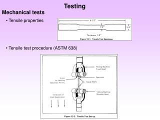
Tensile Test- Basic Principles • An axial force applied to a specimen of original length (lo) elongates it, resulting in a reduction in the cross-sectional area from Ao to A until fracture occurs. • The load and change in length between two fixed points (gauge length) is recorded and used to determine the stress-strain relationship. • A similar procedure can be adopted with a sheet specimen.
Basic Principles • Step 1: Original shape and size of the specimen with no load. • Step 2: Specimen undergoing uniform elongation. • Step 3: Point of maximum load and ultimate tensile strength. • Step 4: The onset of necking (plastic instability). • Step 5: Specimen fractures. • Step 6: Final length.
Lu Lf Basic Principles Primary Test Output: The primary output from a tensile test is the load vs. elongation curve of the specimen, which is recorded in real-time using a load cell and an extensometer. This curve is then used to determine two types of stress-strain curves: • Engineering stress-strain. • True stress-strain.
Terminology Engineering Stress and Strain: • These quantities are defined relative to the original area and length of the specimen. • The engineering stress (e) at any point is defined as the ratio of the instantaneous load or force (F) and the original area (Ao). • The engineering strain (e) is defined as the ratio of the change in length (L-Lo) and the original length (Lo).
Terminology Engineering Stress Strain Curve: • The engineering stress-strain curve (e- e) is obtained from the load-elongation curve. • The yield point, called the yield strength (Y), signifies the start of the plastic region.
Terminology • It is very difficult to find the actual yield strength experimentally. Instead, we use a 0.2% offset yield strength. • 0.2% offset yield strength is the point on the curve which is offset by a strain of 0.2% (0.002) [the intersection of the curve with a line parallel to the linear elastic line and is offset by a strain of 0.002] • The stress at maximum (Fmax/Ao) is referred to as the Ultimate Tensile Strength (TS) and signifies: • the end of uniform elongation. • the start of localized necking i.e. plastic instability.
Terminology Ductility: • Ductility can be defined as the amount of deformation or strain that the material can withstand before failure. For metal forming processes, increasing the ductility increases the material formability . • In general, the ductility of the specimen is defined in terms of the elongation (EL) or the area reduction (AR) before fracture, i.e.:
Terminology True Stress and Strain: • The true stress () uses the instantaneous or actual area of the specimen at any given point, as opposed to the original area used in the engineering values. • The true strain (ε) is defined as the instantaneous elongation per unit length of the specimen. • The relationship between the true and engineering values is given by:
Terminology True Stress and Strain: Note: For a given value of the load and elongation, the true stress is higher than the Eng. Stress, while the true strain is smaller than the Eng. Strain.
Terminology Strain Hardening: • In the plastic region, the true stress increases continuously. This implies that the metal is becoming stronger as the strain increases. Hence, the name “Strain Hardening”. • The relationship between true stress and true strain i.e. the flow curve can be expressed using the power law: where K is called the strength coefficient and n the strain hardening exponent.
Terminology • The plastic portion of the true stress-strain curve (or flow stress curve) plotted on a log-log scale gives the n value as the slope and the K value as the value of true stress at true strain of one. log ()=log(K)+n*log(ε) • For materials following the power law, the true strain at the UTS is equal to n. Strain Hardening:
Terminology Note: when you plot the log-log plot, use datapoints after the yield point (to avoid elastic points) and before instability (necking). • A material that does not show any strain-hardening (n=0) is designated as perfectly plastic. Such a material would show a constant flow stress irrespective of strain. • K can be found from the y-intercept or by substituting n and a datapoint (from the plastic region) in the power law.
Objectives This lab has the following objectives: • Develop an understanding of the basic material properties from the perspective of manufacturing and metal forming. • Determine the material properties by conducting a uniaxial tensile test under ASTM (American Society for Testing and Materials) specifications.
Objectives Students will be able to: • Perform an ASTM standard test (B557), use proper equipment terminology, and know the parameters to control during the test • Collect load vs. elongation data, plot engineering stress vs. strain, determine the modulus of elasticity, ASTM 0.2% offset yield strength, ultimate tensile strength and ductility • Construct a true stress vs. true strain plot and determine the values of K and n for the material tested
Tensile Test • Test Materials and Equipment • Tinius-Olsen universal testing machine. • Tensile specimen (ASTM specifications). • Analog extensometer. • Dial caliper. • Permanent marker. • Safety Equipment and Instructions • Wear safety glasses. • Conduct the test as directed by the instructor.
Tensile Test Tensile testing machine:
Tensile Test Test Specimen: • The tensile test can be conducted with either a round bar or sheet specimen. • The round bar specimen used for the current test complies with the ASTM standards. • A 2 inch gage length is marked on the specimen prior to testing. • The specimen is held in the clamps at either end. Load and movement are applied to the bottom clamp.
Tensile Test Extensometer: • The elongation during testing is measured with respect to the gauge length using an extensometer. • As the specimen elongates, the extensometer reading (elongation of the specimen) is recorded, either real-time or at discrete time intervals. • For the current test, an analog extensometer will be used. Analog Digital
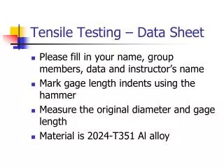
Tensile Test Procedure: • Mark a 2 inch gage length on the tensile test specimen using the dial calipers and marker. • Measure the diameter of the specimen using dial calipers. • Load specimen in the machine grips and remove most of the slack by moving the lower crosshead. • Attach and zero the extensometer; secure it with a lanyard so it will not fall and break if specimen fracture occurs before the extensometer can be removed. • Zero the load indicator and open the right side hydraulic valve about ½ turn.
Tensile Test Procedure (continued): • As the sample is loaded, close the valve and record the load and elongation at regular load intervals (e.g. every 1000 pounds) up to the yield point (when the load starts increasing more slowly and the strain starts increasing more rapidly). • Continue to load the sample until the extensometer range is exceeded, then remove the extensometer. • Continue to load the sample until it breaks; pay close attention to the load indicator and record the load at failure. • Observe and record the maximum load on the follower needle. • Using the dial calipers, measure the final gage length and gage diameter of the fractured specimen (note: when you calculate the fracture strength, use the fracture area calculated from the measured final diameter).
Tensile Test Example Load vs. Elongation (Data obtained from the tensile test): Material Data: Al 6061 Y = 40 ksi TS = 49 ksi
Tensile Test Example Engineering Stress vs. Strain (calculated from Load vs. Elongation data): Material Data: Al 6061 Y = 40 ksi TS = 49 ksi
Tensile Test Example True Stress vs. True Strain (calculated from Engineering stress/strain data): Material Data: Al 6061 Y = 40 ksi TS = 49 ksi
Tensile Test Example Effect of Strain Hardening: • The influence of work/strain hardening on the load vs. elongation during the tensile test can be demonstrated using finite element (FE) analysis. • Consider two materials with the following flow stress data: • Stainless Steel: K = 188 ksi; n = 0.33 • Aluminum Alloy: K = 80 ksi ; n = 0.10. • The tensile test simulations for these two materials show the effect of strain hardening on the load required for deformation and the uniform elongation prior to the onset of necking.
Tensile Test Example Effect of Strain Hardening: K=80 n=0.10 K=188 n=0.33 Stainless Steel Aluminum
Finite Element Analysis (FEA) and Simulations With FEA it is possible to emulate the deformation of various materials that have different flow stress, i.e. K and n values. The next several slides illustrate the simulation of the tensile tests, generated by FEA that simulates the actual deformation of a tensile specimens made of Aluminum 6111-T4.
Tensile Testing Simulation Aluminum 6111-T4 (σ=80.7ε0.23Ksi) Before the test
Tensile Testing Simulation Aluminum 6111-T4 (σ=80.7ε0.23Ksi) Uniform elongation
Tensile Testing Simulation Aluminum 6111-T4 (σ=80.7ε0.23Ksi) Neck formation Instability started
Tensile Testing Simulation Aluminum 6111-T4 (σ=80.7ε0.23Ksi) Necked region Post-uniform elongation
Simulation results- Fracture Comparison of final lengths (total elongation) of specimens at fracture with different n values using FE simulations Fracture occurs after a certain amount of elongation that is influenced by the n-value (a) n=0.2 (b) n =0.4 (c) n = 0.6
Summary – Tensile Testing Lab This lab preparation material introduced: • The basic principles of the tensile test and the terminology used (stress, strain, ductility, strain hardening) • The objectives of and the expected outcomes from the evaluation of test results. • The testing equipment and the test procedure, and • The effect of strain hardening and ductility upon deformation in the tensile test through simulations.