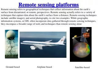
REMOTE SENSING PLATFORMS
REMOTE SENSING PLATFORMS. BALLONS HELICOPTERS AIRPLANES SATELLITES. ORBITS. Geostationary orbit Near Polar orbit (appr.36.000 km) (appr. 500-1000 km). MAJOR EARTH OBSERVING SATELLITES. Landsat SPOT

REMOTE SENSING PLATFORMS
E N D
Presentation Transcript
REMOTE SENSING PLATFORMS BALLONS HELICOPTERS AIRPLANES SATELLITES
ORBITS Geostationary orbit Near Polar orbit (appr.36.000 km) (appr. 500-1000 km)
MAJOR EARTH OBSERVING SATELLITES • Landsat • SPOT • Ikonos • AVHRR • Seawifs • GOES • Meteosat • Terra EOS Satellite (ASTER, MODIS, CERES, MOPITT, MISR)
MAJOR EARTH OBSERVING SATELLITES (contd.) • Radarsat • ESA Satellites (ERS, ATSR) • India Satellites (IRS, LISS, OCM) • Japanese Satellites (JERS, ADEOS, AVNIR, OCTS, MOS, ALOS) • Russian Satellites (Priroda, etc)
LANDSAT Swath Width: 185 km Repeat Cycle 16 days Orbit Altitude: 705 km Equatorial Crossing: at around 10 a.m. local solar time Spectral Bands of Landsat-7
SPOT 4 Characteristics Band (m) Spectral range (µm) Spatial resolution (m) B1 (Green) .500 - .590 20 B2 (Red) .610 - .680 10 and 20 B3 (Near IR) .790 - .890 20 SWIR (MIR) 1.58 - 1.75 20
IKONOS Space Imaging Inc. September 1999
IKONOS Vienna, Austria (enlargement) One-meter pan-sharpened image of Vienna, Austria. Shown here are the Imperial Palace and gardens. This imagery is useful for trans -portation network monitoring, tourism, real estate and other applications Vienna, Austria (full) April 2000
GOES(Geostationary Operational Environmental Satellites) • The GOES series of satellites is the primary weather observation platform for the United States. • The latest generation, GOES I-M, represent an advance in data products for weather forecasting and storm warnings over the previous series of geostationary satellites. • GOES I-M is a 3-axis stabilized system vs. the older spin-scan system, providing more accurate geo-location of earth images.
METEOSAT • Europe's geostationary weather observation satellite • Meteosat was launched in November 1993. • The 4 channel, 3-spectral-band high resolution radiometer constitutes the main payload on board Meteosat. • The radiometer scans in3 spectral bands: Visible, Infrared, and Water Vapor. • The instrument allows continuous imaging of the Earth with images sentevery half-hour.
RADARSAT Canadian Space Agency
RADARSAT Specifications SAR Characteristics Frequency / Wavelength 5.3GHz/C-band 5.6 cm RF Bandwidth 11.6, 17.3 or 30.0 Mhz Transmitter Power (peak) 5 kW Transmitter Power (average) 300 W Maximum Data Rate 85 Mb/s (recorded) - 105 Mb/s (R/T) Antenna Size 15m x 1.5m Antenna Polarization HH Orbit Characteristics Altitude 793-821 kilometres Inclination 98.6 degrees Period 101 minutes Ascending node 18:00 hours Sun-synchronous 14 orbits per day Coverage Access Using Maximum Swath Width North of 70 degrees N Daily North of 48 degrees N Every 4 days The Whole Earth Every 6 days
RADARSAT Specifications (cont.) Imaging Modes MODE NOMINAL NO. OF SWATH INCIDENCE RESOLUTION (m) POSITIONS/BEAMS WIDTH (km) ANGLES (degrees) Fine 8 15 45 37-47 Standard 30 7 100 20-49 Wide 30 3 150 20-45 ScanSAR Narrow 50 2 300 20-49 ScanSAR Wide 100 2 500 20-49 Extended(H) 18-27 3 75 52-58 Extended(L) 30 1 170 10-22
ESA Satellites and Earth Observation System
ATSR (Along Track Scanning Radiometer) • Objective: sea surface temperature, cloud observations, land and ice surface emissivity • Spectral channels: 4 co-registered channels at 1.6, 3.7, 10.8 and 12 micro-meter • IFOV: 1 km x 1 km (nadir), 1.5 km x 2 km (forward view) • Swath width: 500 km
India Satellites and Earth Observation System
IRS-1C The earliest Indian satellite IRS-1C was launched in December 1995 and carried instruments with both high and medium spatial resolutions.
IRS-1D IRS-1D was successfully launched on September 29, 1997. The satellite is an identical twin to IRS-1C. Thus this satellite couple together gives a revisiting cycle of 12 days as opposed to the single-satellite 24-day revisit cycle.
IRS-P3 and IRS-P4 • IRS-P3 is a purely research satellite, successfully launched 21 March, 1996 with WiFS sensor such as IRS-1 C/D with SWIR band at resolution 188 x 246 meter. • IRS-P4 (OCEANSAT-1) was successfully launched 26 May, 1999. The satellite is equipped with two instruments: • OCM ( Ocean Color Monitor ) • Sun synchronous at an altitude of 720 km. • Operating in eight narrow spectral bands, 0.400 - 0.885 micrometer, • A resolution of 350 m and a swath of 1420 km • Used to collect data on chlorophyll concentration, detect and monitor phytoplankton blooms and obtain data on atmospheric aerosols and suspended • sediments in the water. • MSMR ( Multifrequency Scanning Microwave Radiometer ). • A swath of 1360 km • Operating in four microwave frequencies both in vertical and horizontal polarization • Used to collect data on sea surface temperature, wind speed, cloud water content and water vapor content in the atmosphere above the ocean.
Japanese Satellite and Earth Observation System
JERS-1 (Japanese Earth Resources Satellite) • 1. Objective: • Gather data on global land masses while conducting observation for land surveys, agricultural-forestry-fisheries, environmental protection, disaster prevention and coastal surveillance, with emphasis on locating natural resources. • 2. Operation Time : • 1992 - 1998 • 3. Sensors: • SAR (Synthetic Aperture Radar) which is an active microwave sensor • OPS (Optical Sensor) that measures light reflected from the earth's surface ranging from visible light to short-wave infrared light.
ADEOS (Advanced Earth Observing Satellite) • 1. Goal: • Monitoring global environmental changes such as maritime meteorological conditions, atmospheric ozone, and gases that promote global warming • 2. Operation Time : • August 1996 - June 1997 • 3. Sensors: • AVNIR (Advanced Visible Near Infrared Radiometer) • OCTS (Ocean Color and Temperature Scanner) • NSCAT (NASA Scatterometer) • TOMS (Total Ozone Mapping Spectrometer) • POLDER (Polarization and Directionality of the Earth's Reflectance) • IMG (Interferometric Monitor for Greenhouse Gases) • ILAS (Improved Limb Atmospheric Spectrometer) • RIS (Retroreflector In-Space)
AVNIR (Advanced Visible Near Infrared Radiometer) Measurement Objectives: Land and Coastal Zone Scanning Method : Electronic(CCD) Wavelength: Visible( 3 Bands),Near-infrared(1) Panchromatic-Band (visible): 1Bands Spatial Resolution: 16m, Panchromatic-Band:8m Swath Width: 80km
OCTS (Ocean Color and Temperature Scanner) Measurement Objectives: Ocean Color and Sea Surface Temperature Scanning Method: Mechanical Wavelength: Visible: 6 Bands, Thermal-infrared:3 Bands, Middle-infrared: 1 Bands Spatial Resolution: 700m Swath Width: 1400km
MOS (Marine Observation Satellite MOS-1 / MOS-1b) • 1. Objective: • Japan's first marine observation satellite, was launched as a link in a global satellite observation system for more effective natural resource utilization and for environmental protection. • 2. Operation Time: • 1987 - April 1996 • 3. Sensors: • MESSR ( Multi-spectral Electronic Self-scanning Radiometer ) • An electronic scanning radiometer that observes solar light reflected from the earth surface. It is equipped with two camera systems that are set parallel to the satellite's flight direction. • VTIR (Visible and Thermal Infrared Radiometer ) • Using a rotating scanning mirror, the VTIR mechanically scans from right to left at right angle to the satellite's flight direction. • MSR ( Microwave Scanning Radiometer ) • A radio sensor scanning the earth surface along the flight path with its rotating dish antenna.