Download
1 / 70
760 likes | 1k Vues
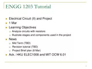
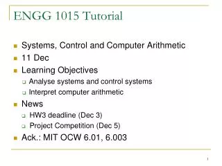
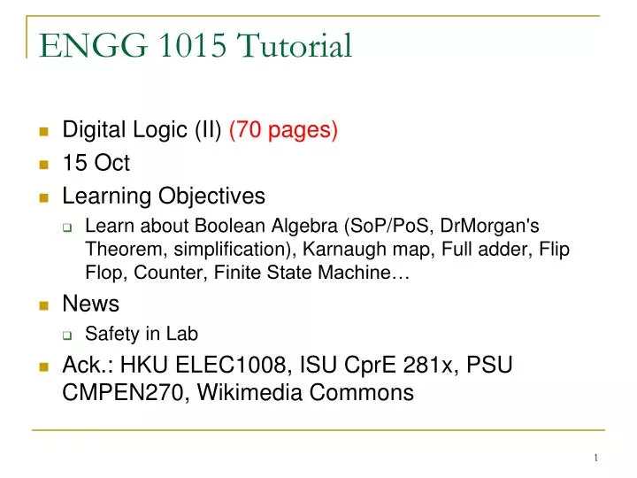
ENGG 1015 Tutorial. Digital Logic (II) (70 pages) 15 Oct Learning Objective s Learn about Boolean Algebra (SoP/PoS, DrMorgan's Theorem, simplification), Karnaugh map, Full adder, Flip Flop, Counter, Finite State Machine… News Safety in Lab

E N D
ENGG 1015 Tutorial • Digital Logic (II) (70 pages) • 15 Oct • Learning Objectives • Learn about Boolean Algebra (SoP/PoS, DrMorgan's Theorem, simplification), Karnaugh map, Full adder, Flip Flop, Counter, Finite State Machine… • News • Safety in Lab • Ack.: HKU ELEC1008, ISU CprE 281x, PSU CMPEN270, Wikimedia Commons
Electrical Safety • 5-10 ma can cause death • Skin resistance can range from 1kΩ for wet skin to 500kΩ for dry skin. • Death can result from as low as 50 volts • Body can sense 9 volts under the right conditions • NO Slippers, NO Sandals in Lab • Report to TA or technician for any emergency case
Boolean Algebra • Boolean Algebra • De Morgan's theorem • Ways for simplification
Digital Logic • Equivalent logic using De Morgan's theorem • AND NOT NOT OR • OR NOT NOT AND • NOT AND OR NOT • NOT OR AND NOT
Quick Checking Any logic function may be implemented by using only OR and NOT gates or only AND and NOT gates
Boolean Algebra Simplification • Sum of Products • How to make “1”? • Better if less “1” • Products of Sum • How to make “0”? • Better if less “0”
Boolean Algebra Using SOP and POS • Find out the expression
Boolean Algebra Using SOP and POS • What about the alternative expression?
Question 1: Boolean Algebra (SoP/PoS) • Find an expression for F and
Solution 1 • Sum of Products for F • Product of Sums for F
Solution 1 • Sum of Products for • Product of Sums for
Question 2: Boolean Algebra (DeMorgan's Theorem) • Use DeMorgan's Theorem to simplify the following expressions
Question 3: Circuit representation of logic equations • Show how can be implemented with one two-input NOR and one two-input NAND gate.
Solution 3 • Show how can be implemented with one two-input NOR and one two-input NAND gate. • (How to convert ?) • We need to apply De Morgan’s Theorem
Question 4: Circuit representation of digital logic • a) Simplify the circuit shown in the figure using Boolean algebra. • b) Change each NAND gate in the circuit of the figure to a NOR gate, and simplify the circuit using Boolean algebra.
Solution 4a Procedure: 1) Obtain the Boolean expression from the circuit2) Check if we need NAND/NOR gate3) Simplify the expression by Boolean algebra and adding double inversion
Solution 4b • First, we convert the circuit
Solution 4b • Then, we simplify the Boolean expression (DeMorgan's Theorem) (Expand) (Simplify) (Group, Group)
Solution 4b (Group, Group) (Simplify) (Expand) (Simplify) (Simplify)
Question 5: Circuit representation of digital logic • Construct the given circuit using NAND gates only • Top down approach: ? • Bottom up approach: ?
Solution 5a • Top down: Expanding the Boolean expression • By DeMorgan’s Theorems,
Solution 5b • Bottom-up: Construct NOT gate, AND gate and OR gate from NAND gate iii) i) ii)
Solution 5b • Top-down and Bottom-up: Same number of gate, same configuration, different approach (cancelled)
Question 6: Conversion of three representations • Describe the function using Boolean expressions • Draw the truth table and describe the function using sum of product
Solution 6 Approach 1: Boolean simplification Find TTApproach 2: Construct TT Find POS (De Morgan) (XOR expansion) (De Morgan) (De Morgan) (expansion) (grouping,expansion) (cancellation) POS:
Quick Checking • Construct NOT gate, AND gate and OR gate from NAND gate iii) i) ii)
Karnaugh map • Draw the table; Fill in 0s and 1s; Grouping • Group one/two/four/eight/sixteen ‘1’(s) only • Use the least number of groups to group all numbers • To group as many numbers as possible in a group
Question 7: Simplification using K-map • Simplify the following Boolean expressions using Karnaugh map.
Solution 7 i) ii)
Question 8: Logic Simplification • Simplify the Boolean expression of the circuit • Change each NAND gate in the circuit to a NOR gate, and simplify the Boolean expression of the circuit
Solution 8a (Expand) (Group) Solve by expression simplification
NQ M 00 01 11 10 0 0 0 1 0 1 0 1 1 0 Solution 8a From truth table to K-map Solve by K-map
Solution 8b Solve by expression simplification
NQ M 00 01 11 10 0 0 1 1 0 1 0 1 1 1 Solution 8b Solve by K-map
Arithmetic Circuit • Half Adder CS=A+B single bit • C: Carry S: Sum • Full Adder CoS=A+B+Ci single bit • e.g. Parallel Adder
Question 9: Full Adder Design • Construct the Boolean expression of a FA • Verify it by constructing a truth table
Solution 9 (Find out expression of S1 and C2)
Solution 9 Any alternative approach?
Solution 9 • Half Adder CS=A+B
Solution 9 • Full Adder CoS=A+B+Ci Find out expression using SOP
NQ M 00 01 11 10 0 0 1 1 0 1 0 1 1 1 Quick Checking • What is the simplest logic expression?
Question 10: Flip Flop (FF) • How many FFs are required to build a binary counter that counts from 0 to 1023? • From “0” to “1023” Range = 1024 • Number of FF required = 10 (since 210=1024) • Determine the frequency at the output of the last FF of this counter for an input clock frequency of 2MHz. • 1,2,…,1024,1,2,…,1024,…,1,2,…,1024 How many times? • With 10 FFs, the range is 1024, therefore, the frequency division at the last FF will be 1/1024 relative to the input check. Thus, output frequency = 2MHz/1024 = 1953 Hz
Question 10 • If the counter is initially at zero, what count will it hold after 2060 pulses? • Every 1024 pulses the counter recycles through zero. Thus, after 2048 pulses the counter is back at count zero. Therefore, after 2060 pulses the counter will be at count 12 (i.e. 2060 = 1024 + 1024 + 12)1,2,…,1024,1,2,…,1024,1,2,…,11,12 2060 pulses
Question 11:Counter • Figure a) shows a complete four-bit parallel adder with registers and b) shows the signals used to add binary numbers from memory and store their sum in the accumulator. Suppose the numbers being added are 1001 and 0101. Also assume that Co=0. Describe what happen at t1, t2, t3, t4 and t5.