Download
1 / 63
630 likes | 852 Vues
BS2 EEPROM Data Storage. When you press ALT-R (run), your program is loaded into the BS2’s EEPROM starting at the highest address (2047) and working down-ward. Most programs don’t use the entire EEPROM, so PBASIC2 lets you store data in the unused lower portion of the EEPROM.

E N D
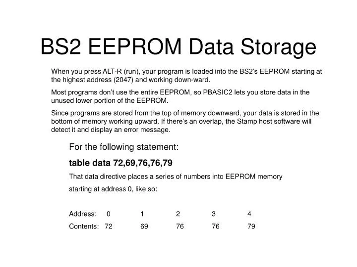
BS2 EEPROM Data Storage When you press ALT-R (run), your program is loaded into the BS2’s EEPROM starting at the highest address (2047) and working down-ward. Most programs don’t use the entire EEPROM, so PBASIC2 lets you store data in the unused lower portion of the EEPROM. Since programs are stored from the top of memory downward, your data is stored in the bottom of memory working upward. If there’s an overlap, the Stamp host software will detect it and display an error message. For the following statement: table data 72,69,76,76,79 That data directive places a series of numbers into EEPROM memory starting at address 0, like so: Address: 0 1 2 3 4 Contents: 72 69 76 76 79
BS2 EEPROM Data Storage 2 PBASIC2 converts quoted text like “A” into the corresponding ASCII character code (65 in this case). You can place quotes around a whole chunk of text used in a Data directive, and PBASIC2 will understand it to mean a series of bytes. The follow-ing three Data directives are equivalent: table1 data 72,69,76,76,79 table2 data “H”,”E”,”L”,”L”,”O” table3 data “HELLO”
Moving the Data Pointer greet data @32,”Hello there” The number following the at sign (@) becomes the initial pointer value, regardless of the pointer’s previous value. Data still automatically increments the pointer value as in previous examples, so Data directives that follow the example above will start at address 43.
Number Representations 2 By default, the BS2 recognizes numbers like 0, 99 or 62145 as being in our everyday decimal (base-10) system. However, you may also use hexadecimal (base-16; also called hex) or binary (base-2). Since the symbols used in decimal, hex and binary numbers overlap (e.g., 1 and 0 are used by all; 0 through 9 apply to both decimal and hex) the Stamp software needs prefixes to tell the numbering systems apart: 99 Decimal (no prefix) $1A6 Hex %1101 Binary
Unary Operators w1 = -99 ' Put -99 (two's complement format) into w1. debug sdec ? w1 ' Display it on the screen as a signed #. w1 = ABS w1 ' Now take its absolute value. debug sdec ? w1 ' Display it on the screen as a signed #.
Examples to Unary Operators w1 = -99 ' Put -99 (two's complement format) into w1. debug sdec ? w1 ' Display it on the screen as a signed #. w1 = ABS w1 ' Now take its absolute value. debug sdec ? w1 ' Display it on the screen as a signed #. N C D Priority encoder of a 16-bit value. NCD takes a 16-bit value, finds the highest bit containing a 1 and returns the bit position plus one (1 through 16).
Branch BRANCH offset, [address0, address1, ...addressN] Go to the address specified by offset (if in range). • Offset is a variable/constant that specifies which of the listed address to go to (0—N). • Addresses are labels that specify where to go. Explanation Branch is useful when you might want to write something like this: if b2 = 0 then case_0 ' b2=0: go to label "case_0" if b2 = 1 then case_1 ' b2=1: go to label "case_1" if b2 = 2 then case_2 ' b2=2: go to label "case_2"
Example for Branch This program shows how the value of the variable pick controls the destination of the Branch instruction. pick var nib ' Variable to pick destination of Branch. for pick = 0 to 3 ' Repeat with pick= 0,1,2,3. debug "Pick= ", DEC pick, cr ' Show value of pick. BRANCH pick,[zero,one,two] ' Branch based on pick. debug "Pick exceeded # of items",cr,"in BRANCH list. Fell through!",cr nextPick: next ' Next value of pick. stop zero: debug "Branched to 'zero.'",cr,cr goto nextPick one: debug "Branched to 'one.'",cr,cr goto nextPick two: debug "Branched to 'two.'",cr,cr goto nextPick
Button 2 BUTTON pin, downstate, delay, rate, bytevariable, targetstate, address Debounce button input, perform auto-repeat, and branch to address if button is in target state. Button circuits may be active-low or active-high. • Pin is a variable/constant (0–15) that specifies the I/O pin to use. This pin will be made an input. • Downstate is a variable/constant (0 or 1) that specifies which logical state occurs when the button is pressed. • Delay is a variable/constant (0–255) that specifies how long the button must be pressed before auto-repeat starts. The delay is measured in cycles of the Button routine. Delay has two special settings: 0 and 255. If Delay is 0, Button performs no debounce or auto-repeat. If Delay is 255, Button performs debounce, but no auto-repeat. • Rate is a variable/constant (0–255) that specifies the number of cycles between autorepeats. The rate is expressed in cycles of the Button routine. • Bytevariable is the workspace for Button. It must be cleared to 0 before being used by Button for the first time. • Targetstate is a variable/constant (0 or 1) that specifies which state the button should be in for a branch to occur. (0=not pressed, 1=pressed) • Address is a label that specifies where to branch if the button is in the target state.
Button Button is designed to be used inside a program loop. Each time through the loop, Button checks the state of the specified pin. When it first matches downstate, Button debounces the switch. Then, in accordance with targetstate, it either branches to address (targetstate = 1) or doesn’t (targetstate = 0). When you press a button or flip a switch, the contacts make or break a connection. A brief (1 to 20-ms) burst of noise occurs as the contacts scrape and bounce against each other. Button’s debounce feature prevents this noise from being interpreted as more than one switch action. (For a demonstration of switch bounce, see the demo program for the Count instruction.)
Example for button Connect the active-low circuit shown in figure I-1 to pin P7 of the BS2. When you press the button, the Debug screen will display an asterisk (*). Otherwise button will jump to nopress and loop will start again. btnWk var byte ' Workspace for BUTTON instruction. btnWk = 0 ' Clear the workspace variable. ' Try changing the Delay value (255) in BUTTON to see the effect of ' its modes: 0=no debounce; 1-254=varying delays before autorepeat; ' 255=no autorepeat (one action per button press). Loop: BUTTON 7,0,255,250,btnWk,0,noPress ' Go to noPress UNLESS.. debug "* " ' ..P7 is 0. noPress: goto loop ' Repeat endlessly.
Count COUNT pin, period, variable Count the number of cycles (0-1-0 or 1-0-1) on the specified pin during period number of milliseconds and store that number in variable. • Pin is a variable/constant (0–15) that specifies the I/O pin to use. This pin will be placed into input mode by writing a 0 to the corresponding bit of the DIRS register. • Period is a variable/constant (1 to 65535) specifying the time in milliseconds during which to count. • Variable is a variable (usually a word) in which the count will be stored.
Count 2 The Count instruction makes a pin an input, then for the specified number of milliseconds counts cycles on that pin and stores the total in a variable. A cycle is a change in state from 1 to 0 to 1, or from 0 to 1 to 0. Count can respond to transitions as fast as 4 microseconds (µs). A cycle consists of two transitions (e.g., 0 to 1, then 1 to 0), so Count can respond to square waves with periods as short as 8 µs; up to 125 kilohertz (kHz) in frequency. For non-square waves (those whose high time and low time are unequal), the shorter of the high and low times must be greater than 4 µs.
Example for Count Connect the active-low circuit shown in figure I-1 (Button instruction) to pin P7 of the BS2. The Debug screen will prompt you to press the button as quickly as possible for a 1-second count. When the count is done, the screen will display your “score,” the total number of cycles registered by count. Note that this score will almost always be greater than the actual number of presses because of switch bounce. cycles var word ' Variable to store counted cycles. loop: debug cls,"How many times can you press the button in 1 second?",cr pause 1000: debug "Ready, set... ":pause 500:debug "GO!",cr count 7,1000,cycles debug cr,"Your score: ", DEC cycles,cr pause 3000 debug "Press button to go again." hold: if IN7 = 1 then hold goto loop
Debug DEBUG outputData{,outputData...} Display variables and messages on the PC screen within the STAMP2 host program. • OutputData consists of one or more of the following: text strings, variables, constants, expressions, formatting modifiers, and control Characters 2 Debug provides a convenient way for your programs to send messages to the PC screen during programming. The name Debug suggests its most popular use—debugging programs by showing you the value of a vari-able or expression, or by indicating what portion of a program is currently executing. Debug is also a great way to rehearse programming techniques. Throughout this instruction guide, we use Debug to give you immediate feedback on the effects of instructions. Let’s look at some examples: DEBUG "Hello World!" ' Test message.
Debug Symbol Value Effect CLS 0 clear Debug screen HOME 1 home cursor to top left corner of screen BELL 7 beep the PC speaker BKSP 8 back up one space TAB 9 tab to the next multiple-of-8 text column CR 13 carriage return to the beginning of the next line Debug "A carriage return",CR Debug "starts a new line"
Debug DEBUG "Hello World!" ' Test message. After you press ALT-R to download this one-line program to the BS2, the STAMP2 host software will put a Debug window on your PC screen and wait for a response. A moment later, the phrase "Hello World!" will appear. Pressing any key other than space eliminates the Debug window. Your program keeps executing after the screen is gone, but you can’t see the Debug data. Another example: x var byte: x = 65 DEBUG dec x ' Show decimal value of x. Since x = 65, the Debug window would display “65.” In addition to decimal, Debug can display values in hexidecimal and binary.
Example for Debug 2 This demo shows the letters of the alphabet and their corresponding ASCII codes. A brief pause slows the process down a little so that it doesn’t go by in a blur. You can freeze the display while the program is running by pressing the space bar. letter var byte Debug "ALPHABET -> ASCII CHART",BELL,CR,CR for letter = "A" to "Z" Debug "Character: ", letter, tab, "ASCII code: ",dec letter, cr pause 200 next
DTMFout DTMFOUT pin,{ontime,offtime,}{,tone...} Generate dual-tone, multifrequency tones (DTMF, i.e., telephone “touch” tones). • Pin is a variable/constant (0–15) that specifies the I/O pin to use. This pin will be put into output mode temporarily during generation of tones. After tone generation is complete, the pin is left in input mode, even if it was previously an output. • Ontime is an optional entry; a variable or constant (0 to 65535) specifying a duration of the tone in milliseconds. If ontime is not specified, DTMFout defaults to 200 ms on. • Offtime is an optional entry; a variable or constant (0 to 65535) specifying the length of silent pause after a tone (or between tones, if multiple tones are specified). If offtime is not specified, DTMFout defaults to 50 ms off. • Tone is a variable or constant (0—15) specifying the DTMF tone to send. Tones 0 through 11 correspond to the standard layout of the telephone keypad, while 12 through 15 are the fourth-column tones used by phone test equipment and in ham-radio applications. 0—9 Digits 0 through 9 10 Star (*) 11 Pound (#) 12—15 Fourth column tones A through D DTMFOUT 0,[6,2,4,8,3,3,3] ' Call Parallax. That instruction would be equivalent to dialing 624-8333 from a phone keypad.
Example for DTMF Parallax, Inc. • BASIC Stamp Programming Manual 1.9 2 EEloc var byte ' EEPROM address of stored number. EEbyte var byte ' Byte containing two DTMF digits. DTdigit var EEbyte.highnib ' Digit to dial. phone var nib ' Pick a phone #. hiLo var bit ' Bit to select upper and lower nibble. Scott data $45,$94,$80,$2F ' Phone: 459-4802 Chip data $19,$16,$62,$48,$33,$3F ' Phone: 1-916-624-8333 Info data $15,$20,$55,$51,$21,$2F ' Phone: 1-520-555-1212 for phone = 0 to 2 ' Dial each phone #. lookup phone,[Scott,Chip,Info],EEloc ' Get location of # in EEPROM. dial: read EEloc,EEbyte ' Retrieve byte from EEPROM. for hiLo = 0 to 1 ' Dial upper and lower digits. if DTdigit = $F then done ' Hex $F is end-of-number flag DTMFout 0,[DTdigit] ' Dial digit. EEbyte = EEbyte << 4 ' Shift in next digit. next EEloc = EEloc+1 ' Next pair of digits. goto dial ' Keep dialing until done ($F in DTdigit). done: ' This number is done. pause 2000 ' Wait a couple of seconds. next ' Dial next phone number. stop
End END End the program, placing the BS2 in a low-power mode. Explanation End puts the BS2 into its inactive, low-power mode. In this mode the BS2’s current draw (exclusive of loads driven by the I/O pins) is approximately 50µA. End keeps the BS2 inactive until the reset button is pushed or the power is cycled off and back on. Just as during Sleep intervals, pins will retain their input or output settings after the BS2 is deactivated by End. So if a pin is driving a load when End occurs, it will continue to drive that load after End. However, at approximate 2.3-second intervals, output pins will disconnect (go into input mode) for a period of approximately 18 ms. Then they will revert to their former states. For example, if the BS2 is driving an LED on when End executes, the LED will stay lit after end. But every 2.3 seconds, there will be a visible wink of the LED as the output pin driving it disconnects for 18 ms.
For...Next FOR variable = start to end {STEP stepVal} ... NEXT Create a repeating loop that executes the program lines between For and Next, incrementing or decrementing variable according to stepVal until the value of the variable passes the end value. • Variable is a bit, nib, byte or word variable used as a counter. • Start is a variable or constant that specifies the initial value of the variable. • End is a variable or constant that specifies the end value of the variable. When the value of the variable passes end, the For…Next loop stops executing and the program goes on to the instruction after Next. • StepVal is an optional variable or constant by which the variable increases or decreases with each trip through the For/Next loop. If start is larger than end, PBASIC2 understands stepVal to be negative, even though no minus sign is used.
Example for “for…next” reps var nib ' Counter for the FOR/NEXT loop. FOR reps = 1 to 10 ' Repeat with reps = 1, 2... 10. debug dec ? reps ' Each rep, show values of reps. NEXT For...Next can also handle cases in which the start value is greater than the end value. It makes the commonsense assumption that you want to count down from start to end, like so: reps var nib ' Counter for the FOR/NEXT loop. FOR reps = 10 to 1 ' Repeat with reps = 10, 9...1. debug dec ? reps ' Each rep, show values of reps. NEXT
Example for “for…next” Parallax, Inc. • BASIC Stamp Programming Manual 1.9 2 Here’s an example that uses a For...Next loop to churn out a series of sequential squares (numbers 1, 2, 3, 4... raised to the second power) by using a variable to set the For...Next stepVal, and incrementing stepVal within the loop. Sir Isaac Newton is generally credited with the discovery of this technique. square var byte ' For/Next counter and series of squares. stepSize var byte ' Step size, which will increase by 2 each loop. stepSize = 1: square = 1 for square = 1 to 250 step stepSize ' Show squares up to 250. debug dec ? square ' Display on screen. stepSize = stepSize +2 ' Add 2 to stepSize next ' Loop til square > 250.
Freqout FREQOUT pin, duration, freq1{,freq2} Generate one or two sine-wave tones for a specified duration. • Pin is a variable/constant (0–15) that specifies the I/O pin to use. This pin will be put into output mode during generation of tones and left in that state after the instruction finishes. • Duration is a variable/constant specifying the length in milliseconds (1 to 65535) of the tone(s). • Freq1 is a variable/constant specifying frequency in hertz (Hz, 0 to 32767) of the first tone. • Freq2is a variable/constant specifying frequency (0 to 32767 Hz) of the optional second tone Freqout generates one or two sinewaves using fast PWM. Examples: FREQOUT 2,1000,2500 FREQOUT 2,1000,2500,3000 The frequencies mix together for a chord- or bell-like sound.
Example for FREQOUT Parallax, Inc. • BASIC Stamp Programming Manual 1.9 i var byte ' Counter for position in tune. f var word ' Frequency of note for Freqout. C con 523 ' C note. D con 587 ' D note E con 659 ' E note G con 784 ' G note R con 0 ' Silent pause (rest). for i = 0 to 28 ' Play the 29 notes of the Lookup table. lookup i,[E,D,C,D,E,E,E,R,D,D,D,R,E,G,G,R,E,D,C,D,E,E,E,E,D,D,E,D,C],f FREQOUT 0,350,f,(f-8) max 32768 next Stop This program plays “Mary Had a Little Lamb” by reading the notes from a Lookup table. To demonstrate the effect of mixing sine waves, the first frequency is the musical note itself, while the second is 8 Hz lower. When sines mix, sum and difference frequencies are generated. The difference frequency imposes an 8-Hz quiver (vibrato) on each note. Subtracting 8 from the note frequency poses a problem when the frequency is 0, because the BS2’s positive-integer math wraps around to 65530. Freqout would ignore the highest bit of this value and generate a frequency of 32762 Hz rather than a truly silent pause. Although humans can’t hear 32762 Hz, slight imperfections in filtering will cause an audible noise in the speaker. To clean this up we use the expression “(f-8) max 32768,” which changes 65530 to 32768. Freqout discards the highest bit of 32768, which results in 0, the desired silent pause.
Gosub GOSUB addressLabel Store the address of the next instruction after Gosub, then go to the point in the program specified by addressLabel. • AddressLabel is a label that specifies where to go. Gosub is a close relative of Goto. After Gosub, the program executes code beginning at the specified address label. (See the entry on Goto for more information on assigning address labels) Unlike Goto, Gosub also stores the address of the instruction immediately following itself. When the program encounters a Return instruction, it interprets it to mean “go to the instruction that follows the most recent Gosub.” Up to 255 Gosubs are allowed per program, but they may be nested only four deep.
Example for GoSub rounds var nib ' Number of reps. numGen var word ' Random-number generator (must be 16 bits). myNum var nib ' Random number, 1-10. for rounds = 1 to 3 ' Go three rounds. debug cls,"Pick a number from 1 to 10",cr GOSUB pickAnumber ' Get a random number, 1-10. pause 2000 ' Dramatic pause. debug "My number was: ", dec myNum ' Show the number. pause 2000 ' Another pause. next stop ' When done, stop execution here. ' Random-number subroutine. A subroutine is just a piece of code ' with the Return instruction at the end. The proper way to use ' a subroutine is to enter it through a Gosub instruction. If ' you don't, the Return instruction won't have the correct ' return address, and your program will have a bug! pickAnumber: random numGen ' Stir up the bits of numGen. myNum = numGen/6550 min 1 ' Scale to fit 1-10 range. ' Go back to the 1st instruction return ' after the GOSUB that got us here.
GOTO GOTO addressLabel Go to the point in the program specified by addressLabel. • AddressLabel is a label that specifies where to go. Programs execute from the top of the page (or screen) toward the bottom, and from left to right on individual lines; just the same way we read and write English. Goto is one of the instructions that can change the order in which a program executes by forcing it to go to a labeled point in the program. A common use for Goto is to create endless loops; programs that repeat a group of instructions ver and over. Goto requires an address label for a destination. A label is a word start-ing with a letter, containing letters, numbers, or underscore (_) charac-ters, and ending with a colon. Labels may be up to 32 characters long. Labels must not duplicate names of PBASIC2 instructions, or variables, constants or Data labels.
Example for GOTO This program is an endless loop that sends a Debug message to your computer screen. Although you can clear the screen by pressing a key, the BS2 program itself won’t stop unless you shut it off. doItAgain: debug "Looping...",cr GOTO doItAgain
HIGH HIGH pin Make the specified pin output high (write 1s to the corresponding bits of both DIRS and OUTS). • Pin is a variable/constant (0–15) that specifies the I/O pin to use. In order for the BS2 to actively output a 1 (a +5-volt level) on one of its pins, two conditions must be satisfied: (1) The corresponding bit of the DIRS variable must contain a 1 in order to connect the pin’s output driver. (2) The corresponding bit of the OUTS variable must contain a 1. High performs both of these actions with a single, fast instruction.
Example for HIGH This program shows the bitwise state of the DIRS and OUTS variables before and after the instruction High 4. You may also connect an LED to pin P4 as shown in figure I-5 to see it light when the High instruction executes. debug "Before: ",cr debug bin16 ? dirs,bin16 ? outs,cr,cr pause 1000 HIGH 4 debug "After: ",cr debug bin16 ? dirs,bin16 ? outs
If...Then IF condition THEN addressLabel Evaluate condition and, if true, go to the point in the program marked by addressLabel. • Condition is a statement, such as “x = 7” that can be evaluated as true or false. • AddressLabel is a label that specifies where to go in the event that the condition is true. If...Then is PBASIC’s decision maker. It tests a condition and, if that condition is true, goes to a point in the program specified by an address label. The condition that If...Then tests is written as a mixture of comparison and logic operators. The comparison operators are: = equal <> not equal > greater than < less than >= greater than or equal to <= less than or equal to
Example for IF aNumber var byte aNumber = 99 IF aNumber < 100 THEN isLess debug "greater than or equal to 100" stop isLess: debug "less than 100" stop When you run that code, Debug shows, “less than 100.” If...Then evalu-ated the condition “aNumber < 100” and found it to be true, so it redirected the program to the label after Then, “isLess.” If you change “aNumber = 99” to “aNumber = 100” the other message, “greater than or equal to 100,” will appear instead. The condition “aNumber < 100” is false if aNumber contains 100 or more.
Input INPUT pin Make the specified pin an input (write a 0 to the corresponding bit of DIRS). • Pin is a variable/constant (0–15) that specifies the I/O pin to use. There are several ways to make a pin an input. When a program begins, all of the BS2’s pins are inputs. Input instructions (Pulsin, Serin) auto-matically change the specified pin to input and leave it in that state. Writing 0s to particular bits of the variable DIRS makes the corresponding pins inputs. And then there’s the Input instruction. When a pin is an input, your program can check its state by reading the corresponding INS variable. For example: INPUT 4 Hold: if IN4 = 0 then Hold ' Stay here until P4 is 1. The program is reading the state of P4 as set by external circuitry. If nothing is connected to P4, it could be in either state (1 or 0) and could change states apparently at random.
Example for Input INPUT 7 ' Make pin 7 an input. debug "State of pin 7: ", bin IN7,cr OUT7 = 0 ' Write 0 to output latch. debug "After 0 written to OUT7: ",bin IN7,cr output 7 ' Make pin 7 an output. debug "After pin 7 changed to output: ",bin IN7 This program demonstrates how the input/output direction of a pin is determined by the corresponding bit of DIRS. It also shows that the state of the pin itself (as reflected by the corresponding bit of INS) is deter-mined by the outside world when the pin is an input, and by the corresponding bit of OUTS when it’s an output. To set up the demo, connect a 10k resistor from +5V to P7 on the BS2. The resistor to +5V puts a high (1) on the pin when it’s an input. The BS2 can override this state by writinga low (0) to bit 7 of OUTS and changing the pin to output.
LOW LOW pin Make the specified pin output low (write 1 to the corresponding bit of DIRS and 0 to the corresponding bit of OUTS). • Pin is a variable/constant (0–15) that specifies the I/O pin to use. In order for the BS2 to actively output a 0 (a 0-volt level) on one of its pins, two conditions must be satisfied: (1) The corresponding bit of the DIRS variable must contain a 1 in order to connect the pin’s output driver. (2) The corresponding bit of the OUTS variable must contain a 0. Low performs both of these actions with a single, fast instruction.
Example for LOW This program shows the bitwise state of the DIRS and OUTS variables before and after the instruction Low 4. You may also connect an LED to pin P4 as shown in figure I-6 to see it light when the Low instruction executes. Dirs = % 10000 ' Initialize P4 to high debug "Before: ",cr debug bin16 ? dirs,bin16 ? outs,cr,cr pause 1000 LOW 4 debug "After: ",cr debug bin16 ? dirs,bin16 ? outs
NAP NAP period ----- Like sleep but not accurate Enter sleep mode for a short period. Power consumption is reduced to about 50 µA assuming no loads are being driven. • Period is a variable/constant that determines the duration of the reduced power nap. The duration is (2^period) * 18 ms. (Read that as “2 raised to the power period, times 18 ms.”) Period can range from 0 to 7, resulting in the following nap lengths: Period 2 period Length of Nap 0 1 18.ms 1 2 36.ms 2 4 72.ms 3 8 144.ms 4 16 288.ms 5 32 576.ms 6 64 1152.ms (1.152 seconds) 7 128 2304.ms (2.304 seconds) Nap uses the same shutdown/startup mechanism as Sleep, with one big difference. During Sleep, the BS2 automatically compensates for varia-tions in the speed of the watchdog timer oscillator that serves as its alarm clock. As a result, longer Sleep intervals are accurate to approxi-mately ±1 percent. Nap intervals are directly controlled by the watchdog timer without compensation. Variations in temperature, supply voltage, and manufacturing tolerance of the BS2 interpreter chip can cause the actual timing to vary by as much as –50, +100 percent (i.e., a period-0 Nap can range from 9 to 36 ms).
OUTPUT OUTPUT pin Make the specified pin an output (write a 1 to the corresponding bit of DIRS). • Pin is a variable/constant (0–15) that specifies the I/O pin to use. There are several ways to make a pin an output. When a program begins, all of the BS2’s pins are inputs. Output instructions (Pulsout, High, Low, Serout, etc.) automatically change the specified pin to output and leave it in that state. Writing 1s to particular bits of the variable DIRS makes the corresponding pins outputs. And then there’s the Output instruction. When a pin is an output, your program can change its state by writing to the corresponding bit in the OUTS variable. For example: OUTPUT 4 OUT4 = 1 ' Make pin 4 high (1). When your program changes a pin from input to output, whatever state happens to be in the corresponding bit of OUTS sets the state of the pin. To simultaneously make a pin an output and set its state use the High and Low instructions.
PAUSE PAUSE milliseconds Pause the program (do nothing) for the specified number of milliseconds. • Milliseconds is a variable/constant specifying the length of the pause in ms. Pauses may be up to 65535 ms (65+ seconds) long. Pause delays the execution of the next program instruction for the specified number of milliseconds. For example: flash: low 0 PAUSE 100 high 0 PAUSE 100 goto flash This code causes pin 0 to go low for 100 ms, then high for 100 ms.
PULSEIN PULSIN pin, state, resultVariable Measure the width of a pulse in 2µs units. • Pin is a variable/constant (0–15) that specifies the I/O pin to use. This pin will be placed into input mode during pulse measurement and left in that state after the instruction finishes. • State is a variable or constant (0 or 1) that specifies whether the pulse to be measured begins with a 0-to-1 transition (1) or a 1-to-0 transition (0). • ResultVariable is a variable in which the pulse duration (in 2µs units) will be stored. You can think of Pulsin as a fast stopwatch that is triggered by a change in state (0 or 1) on the specified pin. When the state on the pin changes to the state specified in Pulsin, the stopwatch starts. When the state on the pin changes again, the stopwatch stops.
Example for PULSEIN This program uses Pulsin to measure a pulse generated by discharging a 0.1µF capacitor through a 1k resistor as shown in figure I-9. Pressing the switch generates the pulse, which should ideally be approximately 120µs (60 Pulsin units of 2µs) long. Variations in component values may produce results that are up to 10 units off from this value. For more information on calculating resistor-capacitor timing, see the RCtime in-struction. time var word again: PULSIN 7,1,time ' Measure positive pulse. if time = 0 then again ' If 0, try again. debug cls,dec ? time ' Otherwise, display result. goto again ' Do it again.
PULSEOUT PULSOUT pin, time Output a pulse of 2µs to 131 ms in duration. • Pin is a variable/constant (0-15) that specifies the I/O pin to use. This pin will be placed into output mode immediately before the pulse and left in that state after the instruction finishes. • Time is a variable/constant (0-65535) that specifies the duration of the pulse in 2µs units. Pulsout combines several actions into a single instruction. It puts the specified pin into output mode by writing a 1 to the corresponding bit of DIRS; inverts the state of that pin’s OUTS bit; waits for the specified number of 2µs units; then inverts the corresponding bit of OUTS again, returning the bit to its original state. An example: PULSOUT 5,50 ' Make a 100-us pulse on pin 5.
Example for PULSEOUT high 0 ' Set the pin high (LED off). again: pause 1000 ' Wait one second. PULSOUT 0,5000 ' Flash the LED for 10 ms. goto again ' Repeat endlessly. This program blinks an LED on for 10ms at 1- second intervals. Connect the LED to I/O pin 0 as shown in figure +5V
PULSE WIDTH MODULATION PWM pin, duty, cycles Convert a digital value to analog output via pulse-width modulation. • Pin is a variable/constant (0-15) that specifies the I/O pin to use. This pin will be placed into output mode during pulse generation then switched to input mode when the instruction finishes. • Duty is a variable/constant (0-255) that specifies the analog output level (0 to 5V). • Cycles is a variable/constant (0-65535) specifying an approximate number of milliseconds of PWM output. Pulse-width modulation (PWM) allows the BS2—a purely digital device to generate an analog voltage. The basic idea is this: If you make a pin output high, the voltage at that pin will be close to 5V. Output low is close to 0V. What if you switched the pin rapidly between high and low so that it was high half the time and low half the time? The average voltage over time would be halfway between 0 and 5V—2.5V. This is the idea of PWM; that you can produce an analog voltage by outputting a stream of digital 1s and 0s in a particular proportion. To determine the proportional PWM output voltage, use this formula: (duty/255) * 5V For example, if duty is 100, (100/255) * 5V = 1.96V; PWM outputs a train of pulses whose average voltage is 1.96V.
RANDOM RANDOM variable Generate a pseudo-random number. • Variable is a byte or word variable whose bits will be scrambled to produce a random number. Random generates pseudo-random numbers ranging from 0 to 65535. They’re called “pseudo-random” because they appear random, but are generated by a logic operation that always produces the same result for a given input. For example: w1 = 0 ' Clear word variable w1 to 0. RANDOM w1 ' Generate "random" number. debug dec ? w1 ' Show the result on screen.
RCTIME RCTIME pin, state, resultVariable Count time while pin remains in state—usually to measure the charge/ discharge time of resistor/capacitor (RC) circuit. • Pin is a variable/constant (0–15) that specifies the I/O pin to use. This pin will be placed into input mode and left in that state when the instruction finishes. • State is a variable or constant (1 or 0) that will end the Rctime period. • ResultVariable is a variable in which the time measurement (0 to 65535 in 2µs units) will be stored. RCtime can be used to measure the charge or discharge time of a resis-tor/ capacitor circuit. This allows you to measure resistance or capaci-tance; use R or C sensors (such as thermistors or capacitive humidity sensors); or respond to user input through a potentiometer. In a broader sense, RCtime can also serve as a fast, precise stopwatch for events of very short duration (less than 0.131 seconds).
READ READ location,variable Read EEPROM location and store value in variable. • Location is a variable/constant (0–2047) that specifies the EEPROM address to read from. • Variable holds the byte value read from the EEPROM (0–255). The EEPROM is used for both program storage (which builds down-ward from address 2047) and data storage (which builds upward from address 0). The Read instruction retrieves a byte of data from any EEPROM address.