Download
1 / 17
220 likes | 483 Vues
NMR Spectroscopy. Tuning / Matching Shimming and Lock. Tuning the probe. Tuning change the resonant frequency Matching adjust the impedance. Tuning Probe. Tuning Probe. Deuterium Lock.

E N D
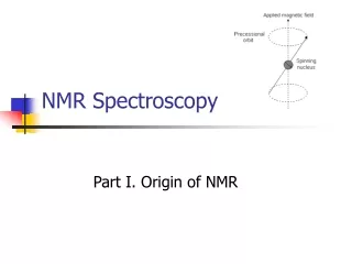
NMR Spectroscopy Tuning / Matching Shimming and Lock
Tuning the probe • Tuning change the resonant frequency • Matching adjust the impedance
Deuterium Lock High resolution NMR measurements require a special field-frequency stabilization to allow accumulation of signals, which may be separated by less than 1 Hz. Lock is to hold the resonance condition by by separate NMR experiment running parallel to the one on the observe channel. Usually the deuterium resonance of the deuterated solvent is used to provide the NMR lock signal. Digital lock: lock signal is fed directly into ADC and displayed on the computer. A narrower lock signals results in higher DC voltage after rectification. By adjusting the various shim currents one aims for an optimum lock signals.
Shimming The process of optimizing the magnetic field homogeneity for recording high resolution spectra is called shimming a magnet. Small coils on pole faces in carefully chosen geometry. Currents in these coils are adjusted. Two types of gradients : spinning (Z0 to Z5) non-spinning (X, Y, …) First order Z1, X, Y Second Order Z2 Higher order Z3, Z4…
Shimming Proton line width in a standard sample should be less than 0.5 Hz with spinner on. Non-spinning proton line width in a 5 mm probe can be easily adjusted to about 2 Hz.
Free Induction Decay (FID) • FID represents the time-domain response of the spin system following application of an radio-frequency pulse. • With one magnetization at w0, receiver coil would see exponentially decaying signal. This decay is due to relaxation.
Sampling the Signal ADC (Analog to Digital Converter) The analogue signal generated in the coil by the sample should be digitized before it can be handled by the computer. The input of ADC is the signal voltage, the output is a binary number proportional to it.
Sampling the Signal Factors determine the performance of ADC • Number of bits the ADC uses to represent the signal voltage • The maximum conversion speed • The number of bits in single word of computer memory
Sampling the Signal • Spectral Width The maximum spectral width is determined by the ADC conversion time which limits the rate of signal sampling. 3-10 ms generates maximum spectral width of 50 kHz to 150 kHz. • Dynamic range The ability of ADC to digitize weak signals faithfully in the presence of string signals. 12 bits to 20 bits are often referred to ADC.
NMR line shape Lorentzian line A amplitude W half-line width