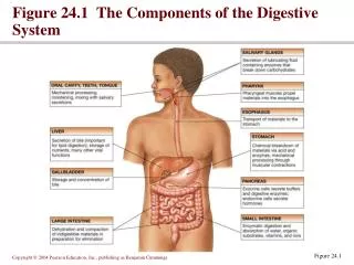
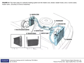
FIGURE 6-2 The components of an automotive heater system. (Courtesy of Everco Industries)
FIGURE 6-1 Winter presents a heat load: Heat must be added for comfort (right). Summer presents a cooling load. FIGURE 6-2 The components of an automotive heater system. (Courtesy of Everco Industries).
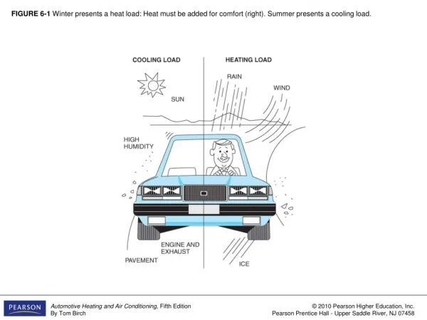

FIGURE 6-2 The components of an automotive heater system. (Courtesy of Everco Industries)
E N D
Presentation Transcript
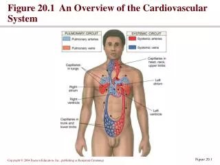
FIGURE 6-1 Winter presents a heat load: Heat must be added for comfort (right). Summer presents a cooling load.
FIGURE 6-2 The components of an automotive heater system. (Courtesy of Everco Industries)
FIGURE 6-3 (a) Heated seats have heating elements under the cover. (b) Electric current passing through the element produces heat.
FIGURE 6-4 A TE element uses semiconductor slabs that either get hot or cool depending on the direction of direct current passing through them.
FIGURE 6-5 Ice has a cooling effect because of latent heat of fusion: It absorbs heat as it melts.
FIGURE 6-6 (a) Both boiling and evaporating liquids absorb the latent heat of vaporization as they change state.(b) This principle is used to cool water in a cloth Lister bag. (Courtesy of Chrysler LLC)
FIGURE 6-7 At one time, evaporative coolers were used to cool car interiors. Air forced through a water-wetted mesh produces evaporation and a cooling effect. (Courtesy of International Mobile Air Conditioning Association,IMACA)
FIGURE 6-8 Heat, from in-car air, causes the refrigerant to boil in the evaporator (left). The compressor increases the pressure and moves refrigerant vapor to the condenser, where the heat is transferred to ambient air. This also causes the vapor to return to a liquid.
FIGURE 6-9 Liquid refrigerant boils and absorbs heat as it enters the lower pressure of the evaporator. The absorbed heat comes from the air passing through the evaporator fins.
FIGURE 6-10 An automotive A/C system in a schematic (a) and somewhat realistic view (b). These views show the relationship of the components and the circulation of the refrigerant.
FIGURE 6-11 When a gas is compressed the heat energy is more concentrated, and this causes a temperature increase.
FIGURE 6-12 In a mechanical refrigeration system, the compressor increases the pressure and causes the refrigerant to circulate through the cycle as shown here.
FIGURE 6-13 Refrigerant enters the condenser as a hot, highpressure gas and leaves as a liquid. Removing heat to ambient air causes the refrigerant to condense.
FIGURE 6-14 Releasing a compressed gas allows the air to expand; the air will be cooled because the heat energy is spread out.
FIGURE 6-15 The Rovac system used a circulator to compress air and to allow the air to expand again. Heat from the compressed air was transferred to ambient air in the hot heat exchanger. Heat from the passenger compartment was absorbed by the expanded air in the cold heat exchanger.