Co-simulation
Co-simulation. Slides from: - Tony Givargis, Irvine, IC253 - Rabi Mahapatra, Texas A&M University - Sharif University. Abstraction. Relative-speed. Verification Time. Real-time. 1. 1 hour. FPGA. 10 -1. ~1 day. Emulator. 100 -1. ~4 days. Behavior (system-level). 1000 -1.

Co-simulation
E N D
Presentation Transcript
Co-simulation Slides from: - Tony Givargis, Irvine, IC253 - Rabi Mahapatra, Texas A&M University - Sharif University
Abstraction Relative-speed Verification Time Real-time 1 1 hour FPGA 10-1 ~1 day Emulator 100-1 ~4 days Behavior (system-level) 1000-1 ~1.4 months Bus functional (system-level) 10000-1 ~1.2 years Cycle accurate (system-level) 100000-1 ~12 years RTL 1000000-1 ~1 lifetime Gate-level 10000000-1 ~1 Millennium Verification via Simulation
Test-vector Generator System Under Test Test-bench Output Monitor Pass/fail Verification via Simulation • Exhaustive simulation • Very slow (previous slide) • Environment modeling • Black box approach • Partial simulation • May not catch all errors • 1984, Pentium fdiv error • Test-vector generation • Slow! • Black box approach
Stop/start simulation at any time Set data values Examine system/environment values at any time Can step through small intervals (i.e., 500 nanoseconds) Simulation setup time (i.e., could spend more time modeling environment than system) Models likely incomplete Simulation speed much slower than actual execution Verification via Simulation
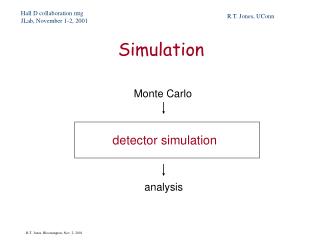
Abstraction levels • Event driven simulation:(gate level simulation) • Most accurate as every active signal is calculated for every device during the clock cycle as it propagates • Each signal is simulated for its value and its time of occurrence • Excellent for timing analysis and verify race conditions • computation intensive and hence very slow • Cycle-based simulation: • Calculate the state of the signals at clock edge(0 or 1) • suitable for complex design that needs large number of tests • 10 times faster than event driven simulation, 20% area efficient
Abstraction levels • Data-Flow Simulator • Signals are represented as stream of values without notion of time. Functional blocks are linked by signals. Blocks are executed when signals present at the input. • Scheduler in the simulator determines the order of block executions. • High level abstraction simulation used in the early stages of verification, typically to check the correctness of the algorithms.
Overcoming Simulation Problems • Reduce amount of real time simulated • 1 msec execution instead of 1 hour • 0.001sec * 10,000,000 = 10,000 sec = 3 hours • Reduced confidence • 1 msec of cruise controller operation tells us little • Faster simulator • Emulators • Special hardware for simulations • Less precise/accurate simulators • Exchange speed for observability/controllability
Overcoming Simulation Problems • Don’t need gate-level analysis for all simulations • Don’t care what happens at every input/output of each logic gate • Simulating RT components ~10x faster • Cycle-based simulation ~100x faster • Accurate at clock boundaries only • No information on signal changes between boundaries • Even faster if using instruction-set simulators • Ideal for processors
HW/SW Co-Simulation • Software is traditionally fully tested after hardware is fabricated => long TTM • Integrating HW and SW earlier in the design cycle => better TTM • Co-simulation involves • Simulating a processor model along with custom hw (usually described in HDL)
High-level Co-simulation • Functional (untimed) simulation allows one to: • check functional (partial) correctness, by generating inputs and observing outputs • debug the design, by easy access to internal states • High-level (timed) co-simulation allows one to check: • feasibility analysis for specification • hardware/software partitioning • architecture selection (CPU, scheduler, ...) • Cannot be used to validate the final implementation • need a much more detailed model of HW and SW architecture
HW/SW Co-Simulation • Variety of simulation approaches exist • From very detailed (e.g., gate-level model) • To very abstract (e.g., instruction-level model) • Simulation tools evolved separately for hardware/software • Software: typically with instruction-set simulator (ISS) • Hardware: typically with models in HDL environment • Integration of GPP/SPP on single IC creating need for merging co-simulation tools
HW/SW Co-Simulation • Simple/naive way • HDL model of microprocessor runs system software • HDL models of specific-purpose processors • Integrate all models • Hardware-software co-simulator • ISS model of microprocessor runs system software • HDL model of specific-purpose processors • Create communication between simulators • Simulators run separately except when transferring data
HW/SW Co-Simulation • Heterogeneous co-simulation environments (C-VHDL or C-Verilog) • RPC or another form of inter-process communication between HW and SW simulators • High overhead due to high data transmission between the simulators
Co-simulation methods (contd) Heterogeneous co-simulation • Network different type of simulators together to attain better speed. • Claims to be actual co-simulation strategy as it affords better ability to match the task with the tool, simulates at the level of details. • Synopsis’s Eaglei: let hw run in many simulators, sw on native PC/workstation or in instruction-set-simulator (ISS). Eaglie tool interfaces all these. SW HW
Heterogeneous co-simulation Homogenous/Heterogenous Product SW ISS (optional) Product SW compute Co-sim glue logic HW Implementation VHDLVerilog Simulation algorithm Event Cycle Dataflow Simulation Engine PC Emulator
Heterogeneous co-simulation • How about performance? • Complex enough to describe any situation • Since software is not running at hardware simulation speed, a better performance will be obtained. • If target CPU is not PC, you may use cross compiler • When software runs directly on PC/WS, runs at the speed of WS • When software can not run directly as processes on WS, you need instruction set simulator ( ISS interprets assembly language at instruction level as long as CPU details are not an issue) • ISS usually runs at 20% of the speed of actual or native processes.
Hardware density of heterogeneous simulation • How much time software accesses hardware? • Hardware density depends on applications and with in an application. • In loosely coupled CPU system, the block responsible for hardware initializations has 30% instructions to access the hardware. • In tightly coupled system, every memory reference could go through simulated hardware. • In general hardware density is important for simulation speed. • The base hardware and tools that communicate between the heterogenous environment can contribute to the speed too. • If simulation is distributed (it often happens these days), the network bandwidth, reliability and speed matters too
Emulation • Special simulation environment with hardware • runs whole design • expensive • 10% of real time • FPGA arrays may be the hardware • allow designers of large products to find a class of problem that cannot be found in simulation • can attach to real devices (router using Quickturn's Ethernet SpeedBridge could route real network traffic)
Emulation • Architectural simulators overlook hardware complexity and lack accuracy • Integration of HDL models with architecture level simulator is pretty slow • Best solution is to implement the Subsystem under Test in FPGA and integrate this with the architecture level simulator
Emulation - How it fits Simulator HDL Description Synthesize Emulation FPGA/ASIC Simulator
Strategy • Simulation speed: Degrades when real components replace the functional blocks. The simulation speed depends on simulation engine, the simulation algorithm, the number of gates in the design, and whether the design is primarily synchronous or asynchronous • Low cost cycle based simulation is a good compromise. Since it can not test physical characteristic of a design, event driven simulator may be used in conjunction. • Cycle based simulators and emulators may have long compilation. Hence, not suitable for initial tests that needs many changes. • Event driven and cycle based simulators have fairly equal debugging environments, all signals are available at all times. Emulators on the other hand, require the list of signals to be traced to be declared at compilation time
Strategy • If the next problem can be found in a few microseconds of simulated time, then slower simulators with faster compilation times are appropriate. • If the current batch of problems all take a couple hundred milliseconds, or even seconds of simulated time, then the startup overhead of cycle based simulation or even an emulator is worth the gain in run time speed. • How about the portability of test benches?
Processor Models • Bus Functional Model (BFM) • Instruction-Set Simulator (ISS)
Bus Functional Model (BFM) • Encapsulates the bus functionality of a processor • Can execute bus transactions on the processor bus (with cycle accuracy) • Cannot execute any instructions • Hence, • BFM is an abstract model of processor that can be used to verify how a processor interacts with its peripherals
At early stages of the design C/C++ BFM In the later stages of the design ISS BFM Assembly SW SW SW SW SW SW HW HW HW HW HW HW Bus Functional Model (cont’d)
Instruction-Set Simulator • ISS: a processor model capable of simulating execution of instructions • Different types of ISS for different purposes • Usage 1: Verification of applications written in assembly-code • For fastest speed: translate target assembly instructions into host processor instructions • Is not cycle-accurate. Specially for pipelined and superscalar architectures
ISS (cont’d) • Different types of ISS … (cont’d) • Usage 2: Verification of timing and interface between system components • Used in conjunction with a BFM • ISS should be timing-accurate in this usage • ISS often works as an emulator • For performance estimation usage, ISS is to provide accurate cycle-counting • To have certain speed improvements, ISS should provide necessary hooks (discussed later)
Integrating an ISS and a BFM • ISS + BFM => complete processor model • Cycle-accurate ISS + (already cycle-accurate) BFM => cycle-accurate processor model • Typical units of an ISS • Fetch, Decode, Execute • Execute unit performs calls to BFM to access memory or configuration registers • Fetch unit performs calls to BFM to read instructions
Integrating an ISS and a BFM (cont’d) • For more complex architectures (pipelined, superscalar) • Other units must be modeled • Cache, prefetch, re-order buffer, issue, … • Many units may need to call BFM functions • ISS may need to provide BFM with certain memory-access functions (discussed later)
Techniques to speedup simulation • Reduce activity on memory bus • Most applications: 95% of memory traffic is attributed to instruction and data fetches • Memory access previously verified? => no need to simulate it again during co-simulation • Put instruction memory (and/or data memory) inside ISS • What to do for external devices accessing instr/data memory? • BFM must be configured to recognize them and call corresponding ISS method to access instr/data • ISS must provide the above methods • ISS must implement a memory map, where certain addresses are directly accessed, while others through bus cycles
Techniques to speedup simulation (cont’d) • Turn off clocks on modules • All clocked components activated by clock edge • Most of time the component is not addressed => activation and simulation (even a limited part of each process) is wasteful => turn off clocks when not necessary • How to do it? • BFM generates bus clock only when devices on the bus are addressed