Co-simulation
Co-simulation. CPSC 617 Hardware-Software Codesign of Embedded Systems. What is HW-SW co-simulation?. Definition: Manipulating simulated hardware with software Why Cosimulation? Design exploration (no trial and error) Enable parallel development of HW and SW components (RTM)

Co-simulation
E N D
Presentation Transcript
Co-simulation CPSC 617 Hardware-Software Codesign of Embedded Systems
What is HW-SW co-simulation? • Definition: Manipulating simulated hardware with software • Why Cosimulation? • Design exploration (no trial and error) • Enable parallel development of HW and SW components (RTM) • Full system integration • Enable replacing of a component late in the design stage • Goal: To verify as much of the product functionality, hardware and software, as possible before fabricating the ASIC. Mahapatra-TexasA&M
Design Exploration Faster prototype is essential for RTM †. †D. Shankar, “Accelerating Architecture Exploration for FPGA Selection and System Design,”Xcell Journal,Issue 58, 2006 Mahapatra-TexasA&M
Overview • In the Past: co-simulation was adopted late in the process, after hardware is deemed to be working and stable. Software developers were often left to develop code for months with severely limited ability to test. • Painful integration process, design flaw and could re-spin the silicon • Now: • Behavioral model simulation has matured, and simulation tools in general have improved to allow better simulation throughout the development cycle • Co-design tools provide project architects with a simulation environment at a very high level of abstraction. Mahapatra-TexasA&M
HW/SW System Integration • Most HW/SW co-designed system are developed using the “plug-and-debug” model: • Once HW/SW partition and communication models are decided, HW team and SW team go on and develop systems independently • When both HW and SW are done, the system is integrated and debugged by lots of logic analyzer probing, “printf” analysis educated guesses etc. Mahapatra-TexasA&M
System Performance Characteristics • We want to know some performance as early as possible in our design process • Processor performance characteristics • Instruction distribution • Cache behavior • Bus (memory) access behavior • Bus traffic behavior, bus transaction turn-around time -Communication distribution among IPs and memory banks • Memory performance characteristics - Memory transactions causing bottlenecks? Mahapatra-TexasA&M
Simulation components 1. Hardware design: Memory, CPU or many ASICs each with one or more CPUs 2. Simulation platform: • PC or workstation. Everything exists as process. • Hybrid platforms with co-processors: off-load part of the load to co-processor, peripheral and test benches remain in software. HW HW, SW HW, SW Mahapatra-TexasA&M
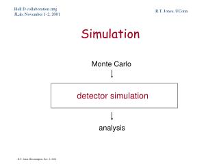
Co-verification How do we verify HW and SW side by side? Software debugger and Logic simulators are used. Mahapatra-TexasA&M
Co-simulation Benefits • Benefits of Co-Simulation • Early access to the hardware design for software engineers • Provide more “realistic” stimulus for hardware simulation (as compared to “unrealistic” testbench waveforms) • Increase controllability and visibility • Increase understanding between hardware and software designers • Some commercial co-simulation tools • Mentor Graphics Seamless & Seamless FPGA • CoWareConvergenSC + Cadence Incisive • Synopsys CoCentric • ARM SoC Designer • Carbon Design Prototype? Mahapatra-TexasA&M
Co-Verification and Co-Simulation • Co-verification can be done on a simulated platform; or an emulated platform • For a simulated platform, simulators of software and hardware are required • For an emulated platform, an FPGA-based development board is often used Mahapatra-TexasA&M
Emulation • Special simulation environment with hardware • runs whole design • expensive • 10% of real time • FPGA arrays may be the hardware • allow designers of large products to find a class of problem that cannot be found in simulation • can attach to real devices (router using Quickturn's Ethernet SpeedBridge could route real network traffic) Mahapatra-TexasA&M
Co-Simulation Algorithms • Event driven simulation:(gate level simulation) • Most accurate as every active signal is calculated for every device during the clock cycle as it propagates • Each signal is simulated for its value and its time of occurrence • Excellent for timing analysis and verify race conditions • computation intensive and hence very slow • Cycle-based simulation: • Calculate the state of the signals at clock edge(0 or 1) • suitable for complex design that needs large number of tests • 10 times faster than event driven simulation, 20% area efficient Mahapatra-TexasA&M
Algorithm contd. • Data-Flow Simulator • Signals are represented as stream of values without notion of time. Functional blocks are linked by signals. Blocks are executed when signals present at the input. • Scheduler in the simulator determines the order of block executions. • High level abstraction simulation used in the early stages of verification, typically to check the correctness of the algorithms. Mahapatra-TexasA&M
Simulation’s Requirement on Hardware • Most simulators can handel behavioral models except the emulators, that require synthesizable codes. • Some simulators may not handel HDLs • Cycle-based simulators can handel asynchronous designs at severe performance penality • Choose simulator (s) in the beginning of design stage. You may use multiple simulators concurrently in a project. • Example: You may use emulator for a problem that requires timing until few hundred microseconds of failure point, then export the state of the system into a simulator. Mahapatra-TexasA&M
Simulator’s requirement on Software • Simulation environment has effects on application software • Programmers certainly need alternate version of application that do not have user interface code or any references to chips that is not part of the simulation environment. • Reduce size of functionality and tables for speed. • Example: consider simulating a 500 MHz processor that initializes a 8KB table, that might take few minutes. Such trivial tasks together consume time but do not add to the quality of the simulators. Mahapatra-TexasA&M
Resolutions of Co-Simulation† †L. Cai and D. Gajski, “Transaction Level Modeling: An Overview,”Proc. of CODES+ISSS, Newport Beach, 2003. Mahapatra-TexasA&M
Different Levels of Abstraction • Functional level • HW/SW independent • Timing is not crucial • Transaction level • SW-like viewpoint of system • Rough timing • Defines both “data token”and “data flow” Mahapatra-TexasA&M
Transaction-Level Modeling • In a transaction-level model (TLM), the details of communication among PEs are hidden in “channel models” • A module is a structural entity with computational processes and transaction processes • Transaction requests take place by calling interface functions of the channel models (each channel can have multiple interfaces) that belong to a port of a module • TLM speeds up simulation and allow implementation freedom through higher level of abstractions Mahapatra-TexasA&M
Simulation Methods • Co-design is a way to simulate at a very high level of abstraction, prior to the actual implementation. These simulations follow the theme of trading details for run-time speed. • By creating a functional model which can be tested, system designers can make sure the requirements are clear. • Making a single model of both hardware and software functionality, the design boundary between the two is effectively removed. • Having a running model also allows engineers to test different hardware/software functionality splits for performance and get some rough timing estimates for various ideas. Mahapatra-TexasA&M
Co-simulation methods: Heterogeneous co-simulation • Network different type of simulators together to attain better speed. • Claims to be actual co-simulation strategy as it affords better ability to match the task with the tool, simulates at the level of details. • Synopsis’s Eaglei: let hw run in many simulators, sw on native PC/workstation or in instruction-set-simulator (ISS). Eaglie tool interfaces all these. SW HW Mahapatra-TexasA&M
Heterogeneous co-simulation Homogenous/Heterogenous Product SW ISS (optional) Product SW compute Co-sim glue logic HW Implementation VHDLVerilog Simulation algorithm Event Cycle Dataflow Simulation Engine PC Emulator Mahapatra-TexasA&M
Heterogeneous cosimulation • How about performance? • Complex enough to describe any situation • Proponents: since software not running hardware simulation speed, in actual the performance will be more. • How fast the software running when not doing hardware related task? • If target CPU is not PC, you may use cross compiler • When software runs directly on PC/WS, runs at the speed of WS • When software can not run directly as processes on WS, you need instruction set simulator ( ISS interprets assembly language at instruction level as long as CPU details are not an issue) • ISS usually runs at 20% of the speed of actual or native processes. Mahapatra-TexasA&M
Hardware density of Heterogeneous simulation • How much time software accesses hardware? • Hardware density depends on applications and with in an application. • In loosely coupled CPU system, the block responsible for hardware initializations has 30% instructions to access the hardware. • In tightly coupled system, every memory reference could go through simulated hardware. • In general hardware density is important for simulation speed. • The base hardware and tools that communicate between the heterogenous environment can attribute to the speed too. • If simulation is distributive (most often it happens these days), the network bandwidth, reliability and speed matters too Mahapatra-TexasA&M
Cosimulation strategies • What you simulate is what you get. Simulation is important for bug free test of the product. The product schedule forces suitable strategies. • Due to decrease in feature size and increase in die size, more functionality are pushed to hardware ( could never happened in the past). Creates challenges for testing due to increased functionality. • Formal design methods, code reviews and code reuse have help. Emulation engine is also of help but expensive. • For typical strategies, we need to know the thoroughness to test and system’s environment. If it involves with health and safety, then detail testing strategy is sought. Mahapatra-TexasA&M
Strategy • Multi-pronged functional test strategy to build levels of assurance • Basic initial tests prove functionality and complex tests are built upon working. • Any single test method has some coverage hole. Event driven tests are closest to the real hardware but its slowness is coverage hole! • Make balance between required test coverage and what might be avoided • A simulation strategy might call for the functional specification to be written as a functional model (co-design). • Hardware designer could use event driven tests for hardware blocks • Software designer could do basic debug using ISS or cross compiler and with fake hardware calls.For detailed functional blocks, software could interface. After, completion of blocks, these can be dropped into the functional model for regression tests. Mahapatra-TexasA&M
Strategy • Simulation speed: Degrades when real components replace the functional blocks. The simulation speed depends on simulation engine, the simulation algorithm, the number of gates in the design, and whether the design is primarily synchronous or asynchronous • Low cost cycle based simulation is a good compromise. Since it can not test physical characteristic of a design, event driven simulator may be used in conjunction. • Cycle based simulators and emulators may have long compilation. Hence, not suitable for initial tests that needs many changes. • Event driven and cycle based simulators have fairly equal debugging environments, all signals are available at all times. Emulators on the other hand, require the list of signals to be traced to be declared at compilation time Mahapatra-TexasA&M
Strategy • If the next problem can be found in a few microseconds of simulated time, then slower simulators with faster compilation times are appropriate. • If the current batch of problems all take a couple hundred milliseconds, or even seconds of simulated time, then the startup overhead of cycle based simulation or even an emulator is worth the gain in run time speed. • How about the portability of test benches? • Test after fabrication? • Fast simulators are useful. Track down the hardware fault is difficult. May patch the problem so as to make the problem reappear easily unless regression tests. Mahapatra-TexasA&M
Strategy • To determining which parts of the system software to run and how much software debug can be done without the hardware. • Software engineer need to go through the code and disable functionality which is too costly for simulation, or if the sequence is important, find ways to reduce its execution time. • The degree of fidelity between the simulated environment and the real world is both a requirement of simulation and a constantly shifting target throughout the simulation effort Mahapatra-TexasA&M
Summary • Issues and trade off discussed • The use of HDLs by programmers and logic designers is good sign of convergence. • Cosimulation is crucial for tightly coupled hardware and software ASICs. • Every project is different with varying objectives. Hence choose the strategy as required. Mahapatra-TexasA&M
How to cosimulate? • How to simulate hardware components of a mixed hardware-software system within a unified environment? • This includes simulation of the hardware module, the processor, and the software that the processor executes. • How to simulate hardware and software at same time? • What are various challenges? • Software runs faster than hardware simulator. How to run the system simulation fast keeping the above synchronized? • Slow models provide detailed and accurate results than fast models. How to balance these effects? • Use of different platforms for simulations. Mahapatra-TexasA&M
Some basic approaches • Detailed Processor Model: • processor components( memory, datapath, bus, instruction decoder etc) are discrete event models as they execute the embedded software. • Interaction between processor and other components is captured using native event-driven simulation capability of hardware simulator. • Gate level simulation is extremely slow (~tens of clock cycles/sec), behavioral model is ~hundred times faster. Most accurate and simple model Gate-Level HDL ASIC Model (VHDL Simulation) software (Backplane) Mahapatra-TexasA&M
Some basic approaches • Bus Model (Cycle based simulator): • Discrete-event shells that only simulate activities of bus interface without executing the software associated with the processor. Useful for low level interactions such as bus and memory interaction. • Software executed on ISA model and provide timing information in clock cycles for given sequence of instructions between pairs of IO operation. • Less accurate but faster simulation model. Software executed by ISA Model ASIC Model (VHDL Simulation) Bus Function Model HDL Program running on Host (Backplane) Mahapatra-TexasA&M
Some basic approaches • Instruction Set Architecture Model: • ISA can be simulated efficiently by a C program. C program is an interpreter for the embedded software. • No hardware mode. Software executed on ISA model. Execution on ISA model provides timing (clock) details of the cosimulation. • Can be more efficient than detailed processor modeling because internals of the processor do not suffer the expense of discrete-event scheduling. ISA Modell C program ASIC Model (VHDL Simulation) Program Running on Host software (Backplane) Mahapatra-TexasA&M
Some basic approaches • Compiled Model: • very fast processor models are achievable in principle by translating the executable embedded software specification into native code for processor doing simulation. (Ex: Code for programmable DSP can be translated into Sparc assembly code for execution on a workstation) • No hardware, software execution provides timing details on interface to cosimulation. • Fastest alternative, accuracy depends on interface information. ASIC Model (VHDL Simulation) Software compiled for native code of the host Program running on host (Backplane) Mahapatra-TexasA&M
Some basic approaches • Hardware Model: • If processor exists in hardware form, the physical hardware can often be used to model the processor in simulation. Alternatively, processor could be modeled using FPGA prototype. (say using Quickturn) • Advantage: simulation speed • Disadvantage: Physical processor available. ASIC Model (VHDL Simulation) FPGA Processor (Backplane) Mahapatra-TexasA&M
A New Approach • This is a combined HW/SW approach. The host is responsible of having OS, some applications and might have superset simulating environment (RSIM, SIMICS, SIMOID). • Use of fast backplane (PCI) for communication. Real processor or processor core in FPGA as hardware model, and ASIC/FPGA for interface and interconnection for hardware modeler. • Good for fast complex architecture simulations including multiprocessor. Host with ISA Simulator Processor or FPGACore Interface Logic in FPGA PCI Bus Mahapatra-TexasA&M
Domain coupling • In four out of six approaches, we have host that run software and required to interact with hardware model or simulator. • Difficulties: • providing timing information across the boundaries • coupling two domains with proper synchronization Mahapatra-TexasA&M
Migration across cosimulation • Consider the system simulation at different levels of abstraction throughout the design process: • In the beginning of design process, hardware synthesis is not available. Hence use functional model to study the interaction between HW and SW. • As design progress with more implementations, replace functional model of hardware by netlist level. • Once detail operation of hardware is verified, swap back the high level description of HW design to gain simulation speed. • The cosimulation environment should have this migration support across the levels of abstraction. • Off-the-shelf Components: design is not a part of the current design process. Functional model is enough, no need to know internal details. Mahapatra-TexasA&M
Master slave cosimulation • One master simulator and one or more slave simulators: slave is invoked from master by procedure call. • The language must have provision for interface with different language • Difficulties: • No concurrent simulation possible • C procedures are reorganized as C functions to accommodate calls HDL Master HDL Interface Slave C simulator Mahapatra-TexasA&M
Distributed cosimulation • Software bus transfers data between simulators using a procedure calls based on some protocol. • Implementation of System Bus is based on system facilities (Unix IPC or socket). It is only a component of the simulation tool. • Allows concurrency between simulators. C program Interface to software Bus VHDL Simulator VEC Interface to Software Bus Cosimulation (Software) Bus Mahapatra-TexasA&M
Synchronization and Time in cosimulation • In case of a single simulator (say Verilog) there is no problem for timing as single event queue is managed for simulation. • If there are several simulators and software programs in the domain: • hardware and software domain are using a handshaking protocol to keep their time (clock) synchronized. Signals (events) transferred from one side to the other should have attached a time stamp. • It is possible to use a loosely coupled strategy which allows the two domain to proceed more independently. If a signal is received with a time stamp lower than the current clock in the respective domain, the respective simulator have to be back up. Mahapatra-TexasA&M
Aspects of cosimulation • A frame work of cosimulation consists of variety of components, levels of abstractions and different models. Functional Model Functional Model . . Instruction-set model Analog model . . Netlist-level Detail arch. model Mahapatra-TexasA&M
Heterogeneous Environment: Ptolemy • Ptolemy supports different design styles encapsulated in objects called Domain. • Domain realizes a computational model appropriate for a particular sub-system. Ex: SDF, Dynamic Dataflow(DDF), Discrete Event(DE) and Digital hardware modeling environment (Thor). • Domain consists of a set of Blocks and Schedulers that confirm to a common computational model. • Geodesic • initialize() • numlnit() • setSourcePort() • setDestPort() • Block: • setup • go() • wrapup() Geodesic Block Block PortHole PortHole PortHole PortHole Particle • PortHole • initialize() • receiveData() • sendData() • Particle • readType() • print() • operator <<() • clone() Block objects send and receive data encapsulated in particles to outside world through PortHoles. Buffering: by Geodesic Garbage Collection: Plasma Plasma Mahapatra-TexasA&M