Synchrotron Radiation: A Future Retrospective
610 likes | 1.03k Vues
Synchrotron Radiation: A Future Retrospective. Symposium in Honor of Iran Thomas May 2003 Sunil K.Sinha UCSD/LANL. Where were we in 2003?. Over 8000 users at 4 DOE Light Sources. Methods of obtaining structures with X-Rays.

Synchrotron Radiation: A Future Retrospective
E N D
Presentation Transcript
Synchrotron Radiation: A Future Retrospective Symposium in Honor of Iran Thomas May 2003 Sunil K.Sinha UCSD/LANL
Where were we in 2003? • Over 8000 users at 4 DOE Light Sources
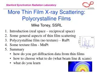
Methods of obtaining structures with X-Rays • Scattering--beam can be large, but measures spatially and time-averaged snapshots of F.T. of instantaneous correlations ( no phase information) • EXAFS/NEXAFS/DAFS ( local order)
Previous and Current Accomplishments • Structure of Physisorbed and Chemisorbed Layers and 2D Phase Transitions. • Liquid Crystal Phases and Phase Transitions • Structure of Nanowires, Quantum Dots, Magnetic Dot and Hole Arrays. • Structures of Surface Reconstruction, Thin Films, Liquid Surfaces, Confined fluids • Magnetic multilayers and interfaces
New types of Charge, Spin and Orbital Ordering and Polarons in Complex Oxides: Manganites, Hi-Tc S/C, etc.
Imaging ---limited by size to which we can focus beam down to. Depends on Source Brilliance. Current limit 0.1 microns (Hard X-Rays), 35 nm (Soft X-Rays)
Microbeam studies of Residual Strain in Materials • Schematic drawing of an x-ray microbeam experiment. Curved mirrors focus the synchrotron x rays down to a diameter of less than one micron on the sample. The microbeam penetrates each layer of the sample, and an area detector measures the directions of the scattered x rays. Here, the sample consists of a roll-textured nickel substrate covered with two epitaxial films: a buffer layer and a superconductor (YBCO). The detector image provides a grain-by-grain description of the atomic structure, orientation, and strain of each layer.
Schematic of a scanning x-ray nanoprobe using zone plate focusing. Example----Element specific Imaging of Cells
What is exchange bias? W.H. Meiklejohn, C.P. Bean, Phys Rev., 105, 904(1957). J. Nogués, Ivan K. Schuller, J. of Magn. Magn. Mater.,192, 203 (1999).
bit line current produces easy axis field Small sense current flows through bit digit line current produces hard axis field Isolation Transistor “OFF” Isolation Transistor “ON” • MR=37% • Write at 4mA digit line and 3.2mA bit line current “Read Mode” “Write Mode”
HCF Random-field, domain state, etc., models Super exchange (AF-coupling) Frustrated super exchange (AF-coupling) -1 +1 -’ve HE +’ve HE HCF 10nm U. Nowak et. al., J. Magn. Magn. and Mater.,240, 243 (2002). A.P. Malozemoff, J. Appl. Phys., 63, 3874 (1988).
Sample (1-10 mm) can be in air, water, or any low-absorption substance. Detector system f scintillator 0.5 m X-rays CCD/video Lens f x x Motion stages y y z Experimental set-up
X-ray Photoemission Spectroscopy • Energy Bands and Fermi Surfaces of important materials --XPES/SPXPES • Symmetry of S/C Order Parameter and Electron Phonon coupling in Hi-Tc S/C
Metal Clusters and Magnetism; From Atoms to Solids(Nora Berrah/ALS) Electrons Mott Scattering
Metal Clusters and Magnetism Mott Polarimeter Detection • Measure the spin component parallel to the photon • Electron emitted perpendicularly to the photons, at 45 with respect to the storage ring plane.
IXS measures S(q,) to ~2meV resolution (t≤ ps.) • Phonons in Liquids, Glasses, Quantum Crystals, Semiconductors, Metals • Electronic Excitations in metals, Hi-Tc Oxides, Spin-Peierls Chains, Mott Insulators
X-Ray Photon Correlation Spectroscopy (XPCS)--measures time scales greater than ms.Dynamics of Colloids, Liquid Surfaces
Pump-Probe Expts.---measures response on time scales ns. or greater.
Microscope 50 nm resolution Triggering pump < 1 ps resolution 10 m Time resolved probe <100 ps resolution J.Stohr, A.Scholl et al./SSRL Photoconductive switch • Sample Deposition • sputter deposition (CXRO) • e-beam evaporation (PEEM) • Waveguide Structure • - photo-lithography, lift-off (UCB microlab) • Patterning • Focused Ion Beam (FIB) etching (NCEM) Conducting wire Magnetic Cells Substrate: GaAs Current
Ground plane GaAs waveguide H 10 mm Waveguide: 200 nm Cu Pattern: 20 nm Co90Fe10 Gradient image Movie H XMCD image Time 1 mm
X-Ray Waveguides • Capable of focusing hard X-Ray beam down to <50nm • In 1- or 2-D
Geophysics and Environmental Science • Diamond Anvil Cell coupled with small bright beams enabled studies of structure (phases).dynamics (Equation of State) of minerals in earth’s mantle and core; new phases of Hydrogen,ice, etc. • Fluorescence Microtomography yielded information on transfer of elements into environment, etc.
Ultimate Goal Can we image actual atoms (and maybe electrons) in real space and time?
Why go lensless?(Courtesy of Janos Kirz) • A technique for 3D imaging of 0.5 – 20 µm isolated objects • Too thick for EM (0.5 µm is practical upper limit) • Too thick for tomographic X-ray microscopy (depth of focus < 1 µm at 10 nm resolution for soft X-rays even if lenses become available) • Goals • <10 nm resolution (3D) in 1 - 10µm size biological specimens • (small frozen hydrated cell, organelle; see macromolecular aggregates) • Limitation: radiation damage! • 2 nm resolution in less sensitive nanostructures • (Inclusions, porosity, clusters, composite nanostructures, aerosols…) • eg: molecular sieves, catalysts, crack propagation
Image reconstruction from the diffraction pattern • Lenses do it, mirrors do it • – but they use the full complex amplitude! • Recording the diffraction intensity leads to the • “phase problem”! • Holographers do it – but they mix in a reference wave, need very high resolution detector or similar precision apparatus • Crystallographers do it – but they use MAD, • isomorphous replacement, or other tricks • (plus the amplification of many repeats)
“Oversampling”: Non-crystals: pattern continuous, can do finer sampling of intensity Finer sampling; larger array; smaller transform; “finite support” (area around specimen must be clear!) Miao thesis
Reconstruction Equations can still not be solved analytically Fienup iterative algorithm Reciprocal space Real space Impose diffraction magnitudes Impose finite support • Positivity of electron density helps! Miao thesis
DIFFRACTION IMAGING BY J. MIAO ET AL • 2-D reconstruction with Fienup-type algorithm • Both levels show because the depth of focus is sufficient • Resolution = 8 nm (new record) • From Miao, Ishikawa, Johnson, Anderson, Lai, Hodgson PRL Aug 2002 • SEM image of a 3-D Ni microfabricated object with two levels 1 µm apart • Only top level shows to useful extent • Diffraction pattern taken at 2 Å wavelength at SPring 8 from Howells
MIAO ET AL 3-D RECONSTRUCTIONS • Miao et al 3-D reconstruction of the same object pair • a and b are sections through the image • cis 3-D density • Resolution = 55 nm
JCHS 7 Successful reconstruction of image from soft X-ray speckle alone. SEM Image X-ray reconstruction 50 nm diameter Gold Balls on transparent SiN membrane. No “secondary image” was used Approximate object boundary obtained from autocorrelation fn. *How to make an isolated object ? Use AFM to remove unwanted balls. He, Howells, Weierrstall, Spence Chapman, Marchesini et al. Phys Rev B In press. 03, Acta A.59, 143 (2003).
I.K. Robinson et al. gold nanocrystals 7.5 KeV beam at the APS PRL 87, 195505 (2001)
New apparatus:Diffraction patterns from yeast cells D. Shapiro et al., Stony Brook
Rapid development of accelerator technology, laser technology, X-Ray Physics and Scientific Knowledge will usher in a Revolution over the next 2 decades.
In the Decades after 2003….Upgraded Rings,LCLS,LUX,CIRCE,TJFELXFEL • Brilliances increase by 3-12 orders of magnitude • Femtosecond X-Ray pulses/attosecond pulses • Total transverse coherence • Photon degeneracies go from 0.4 to 1010
t= t=0 Aluminum plasma classical plasma G =1 G =10 dense plasma G =100 high density matter 1 - 4 - 2 2 4 10 10 10 10 Density (g/cm-3) Femtochemistry Nanoscale Dynamics inCondensed matter Atomic Physics Plasma and Warm Dense Matter Structural Studies on Single Particles and Biomolecules FEL Science/Technology • Presented to BESAC 10-Oct-2000 Science Assessment • Critical Decision 0 approved • 13-June 2001 Program developed by international team of scientists working with accelerator and laser physics communities “the beginning.... not the end”
Single molecule imaging? • Atomic resolution structures known for few mammalian membrane proteins! • Collect many single molecule diffraction patterns from fast x-ray pulses, and reconstruct? • Lysozyme explodes in ~50 fsec • R. Neutze et al., Nature406, 752 (2000)
Undulator Seed laser Ebeam log (power) Saturation Distance FEL Interaction Electron slips backwards one wavefront per undulator period Electrons are bunched under the influence of the light that they radiate. The bunch dimensions are characteristic of the wavelength of the light.
100 mJ - 1 mJ @ 800 nm XUV @ 3 – 30 nm h = 10-8 - 10-5 t Propagation Recombination 0 wXUV x tb -Wb Ionization Energy Laser electric field High-Harmonic Generation Noble Gas Jet (He, Ne, Ar, Kr)
High Gain Harmonic Generation Method to reach short wavelength FEL output from longer wavelength input seed laser. Input seed at w0 overlaps electron beam in energy modulator undulator. Energy modulation is converted to spatial bunching in chicane magnets. Electron beam radiates coherently at w3 in long radiator undulator. Radiator is tuned to w3. Modulator is tuned to w0. Electron beam develops energy modulation at w0. 3rd harmonic bunching is optimized in chicane.
Output at 3w0 seeds 2nd stage Output at 9w0 seeds 3rd stage Final output at 27w0 Input seed w0 3rd stage 1st stage 2nd stage Cascaded HGHG • Number of stages and harmonic of each to be optimized during study. • Factor of 10 – 30 in wavelength is reasonable without additional acceleration between stages. • Seed longer wavelength (100 – 10 nm) beamlines with ~200 nm harmonic from synchronized Ti:Sapp laser. • Seed shorter wavelength (10 – 0.3 nm) beamlines with HHG pulses.
Main oscillator Fiber link synchronization UV Hall X-ray Hall Seed laser Pump laser Seed laser Pump laser Undulators 100 nm Undulators 30 nm 1 nm Injector laser 10 nm 0.3 nm SC Linac 0.3 nm SC Linac 0.1 nm 1 GeV 2 GeV 4 GeV 10 nm Upgrade: 0.1 nm at 8 GeV 3 nm 1 nm Undulators Seed laser Pump laser Nanometer Hall MIT X-ray Laser Concept
HISTORY of ADVANCES in ULTRASHORT PULSE DURATION rotation 10ps Nd:glass Nd:YLF Nd:Y AG Diode S-P Dye Dye 1ps vibration SOLID-STATE CW Dye REVOLUTION SHORTEST PULSE DURATION Color Center 100fs Cr:LiS(C)AF CP M Dye Er:fiber DYE LASER Cr:YAG Nd:fiber BREAKTHROUGHS Cr:forsterite w/Compression 10fs Ti:sapphire electronic “new” era: attophysics 1fs 1965 1970 1975 1980 1985 1990 1995 2000 2005 Vienna YEA R Saclay/FOM 100as First laser atomic unit of time 24 as First passive modelocking 10as 1970 1975 1980 1985 1990 1995 2000 2005 YEAR
BREAKING THE fs BARRIER 100 nm (50 THz) 100 as 5,000 THz !!! time • Uncertainty Principle: t need bandwidth !! • Control phases of field e.g. mode-locked • Attosecond metrology
MEASURING ULTRASHORT PULSES delay line • autocorrelation: determine I(t). A() Prism (x) PMT 2 time BS (2) • Criteria: • nonlinear media, e.g. (2), (3) • adequate peak power • NL interferometric techniques: complete determination of E,.FROG, TAPOLE, SPIDER, etc. • These techniques are applicable throughout the visible and near IR and UV.
ATTOSECOND SIDEBAND CROSS-CORRELATION HHG photoionization HHG + fundamental • sidebands are XUV+ocross-correlation. • scan delay between XUV and o . • amplitude or energy modulation. • analysis is model dependent. H17 e energy H17 e energy electrons electrons H13 H13 gnd gnd
TRAIN of ATTOSECOND PULSES sideband amplitude -4 -2 0 1 delay (fs) P. M. Paul et al., Science 292, 1689 (2001)