Audio Impedance Meter
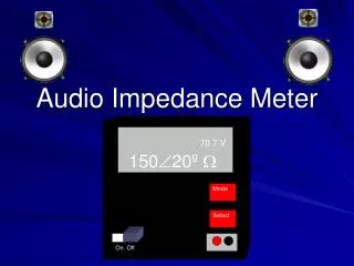
Audio Impedance Meter. 70.7 V 150 20 º . Mode. Select. On Off. Team Leader Kendrick Taylor Group Members Terrence Carter Keithric Taylor Milton Naylor. Design Team Advisor Dr. Noel Schulz Sponsor Mr. Martin F. Jue (MFJ Enterprises).

Audio Impedance Meter
E N D
Presentation Transcript
Audio Impedance Meter 70.7 V 15020º Mode Select On Off
Team Leader Kendrick Taylor Group Members Terrence Carter Keithric Taylor Milton Naylor Design Team Advisor Dr. Noel Schulz Sponsor Mr. Martin F. Jue (MFJ Enterprises) Design Team Members
Abstract We plan to design a digital impedance meter that will be used during installation and for troubleshooting of speaker systems. This handheld device will display the measured impedance, power, and voltage of a speaker system.
Problem Statement • Speaker systems are used throughout the world, so it is important that they are installed properly. • It is essential that the impedance ratings on the amplifier and speakers match.
Problem Statement (Cont.) If the wrong impedances are presented to the amplifier, the following problems can arise: • Damage to the amplifier • Damage to the speaker • Inefficient operation • Uneven sound distribution • Distorted sound
Solution A low cost, portable impedance meter. A handheld digital impedance meter will give the system installers the required device to match the impedances of the speakers and the amplifier.
Implementation Audio Power Amplifier Speaker System 70.7 V 15020º Speaker System Mode Select On Off
User-Interface • The LCD shows the user both the Impedance and calculated value. • Mode button switches between Impedance mode and Calculator mode. • Select button toggles between input values. 70.7 V 15020º Calculator P (Watts) V (Volts) 0000 0000 Mode Select On Off
Design Constraints • Measurement Ranges • 5 - 200 k impedance range • 25, 50, 70.7, 100 volt speaker system • Internal Calculator • Calculates power and voltage • Voltage Requirement • 9V Battery • Filter • Converts 1kHz PWM to a 1kHz sine wave
Design Constraints (Cont.) • Driver Amplifier • Increases the signal to 5 volts • Connections • Two 15” test leads with alligator clamps • Weight • Less than 2 pounds • Packing Size • 6’’ x 4’’ x 2’’ (L x W x H)
Hardware Block Diagram Data PIC Active Filter Driver Amplifier Rectifier LCD Power Supply
PIC Data -Pulse-width modulation 1 kHz signal -Controls LCD PIC Active Filter LCD Display Voltage
PIC (Cont.) • The type of PIC used will be the PIC16C63. • Use voltage measurements to solve for the unknown impedance • Generates 1 kHz PWM
Functional Diagram PIC Active Filter
Active Filter Opamp LM324 Bandpass Filter • Center frequency of 1kHz • Multiple feedback • Eliminate harmonics
Functional Diagram PIC Active Filter Driver Amplifier
Driver Amplifier Class-A Low-Power • Increases the incoming signal to 5 volts and power to 1 watt • Drives the signal through the impedance load
Functional Block Diagram PIC Active Filter Driver Amplifier Rectifier
Rectifier Circuit • AC – DC conversions • Schottky Diode • Half-wave rectifier • Voltage outputs are relayed back to the PIC
Power P = V2/Z Voltage V = (P*Z) Magnitude of Impedance Z = Xs (Vz/Vs) Phase of Impedance Sin = (Vin2 -Vs2 - Vz2) (2*Vs*Vz) Calculations Performed by PIC
Functional Diagram PIC Active Filter Audio Driver Amplifier Rectifier LCD
Summary • Digital handheld device • Installing and troubleshooting speaker systems • Impedance Measurement • Displayed in polar form • Internal Calculator • This unit calculates a power value based on impedance and voltage, or calculates a voltage value, based on impedance and power.
Questions ???