Download
1 / 6
60 likes | 230 Vues
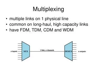
Multiplexing with the 1720 Digitizer. Setup. 0. Digitizer. fifo. I). 1. amp. 2. We send the same signal into 3 channels of the digitizer to make sure each sees the same thing and we see the same pulses from all 3 channels. 0. Digitizer. fifo. II). amp. fifo. 1. 2. fifo.

E N D
Setup 0 Digitizer fifo I) 1 amp 2 We send the same signal into 3 channels of the digitizer to make sure each sees the same thing and we see the same pulses from all 3 channels 0 Digitizer fifo II) amp fifo 1 2 fifo multiplexed data Some of the data are multiplexed. The bigger picture is that each digitizer channel can handle 2 or 3 PMTs if we multiplex them and electronics become cheaper, but it also should perform as well with the multiplexed data as it does with the non-multiplexed.
Single PMT into 3 Different Digitzer Channels Ratios of measured integral in each channel to the measured integral in channel 0 on an event by event basis. Channel 0 Channel 1 Channel 2 Up to 1 % change depending on which channel is selected from the digitizer. Energy spectrum from constant time integral
Single PMT- Undelayed, Delayed, Delayed and Multiplexed time T time T Ratio 1/0 Ratio 2a/0 Ratio 2b/0 Ratio 2b/1 integral_0 Channel 0 Delay D integral_1 Channel 1 Channel 2 integral_2a integral_2b Same energy spectrum as previous page constant time integral Various ratios of const time width integrals. Ratio of delayed intgrals and ratio of undelayedintegrals are ~ .5% FWHM. While comparing undelayed to delayed are much worse, ~4% FWHM with large tails. The delay is ~200 ns nd the integral window is ~120ns.
Signal Defects After Pulsing All of these examples fall into the delayed signal integral window, which is very common thing. Though all of these are from the single PMT into 3 digitizer channels, hence the three graphs of the same picture. After Pulsing + Ringing Ringing + Noise
Lower Threshold 137Cs Compton Edge Background 40K Compton Edge Noise (radio station), PMT ringing, and PMT after pulses shows up more for the lower size signals, hence the worse resolution of the various ratios. High threshold energy spectrum from constant time integral