LOGIC GATES
400 likes | 2.01k Vues
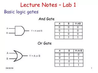
Logic gates are the basic building blocks of any digital system. It is an electronic circuit having one or more than one input and only one output. The relationship between the input and the output is based on a certain logic. Based on this, logic gates are named as AND gate, OR gate, NOT gate etc.

LOGIC GATES
E N D
Presentation Transcript
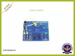
LOGIC GATES ELECTRONICS2
ABOUT ME ABU BAKAR NATIONALITY : PAKISTAN CITY : SIALKOT, PUNJAB MARITAL STATUS : SINGLE Tel: (+92) 322 7967172 E-Mail: abubakarmehmood786@yahoo.com CONTACT INFO PERSONAL PROFILE THE CREATOR ACADEMY thecreatorsacademyofficial The Creators Academy thecreatorsacademyofficial BS(HONS) PHYSICS UNIVERSITY OF SIALKOT UCQxAo-GBHUI2l9_LBYicsRw FOUNDER EDUCATION ORIGIN LAB, VIRTUAL LAB, ENDNOTE SOFTWARE, EMATHHELP SOFTWARE , MICROSOFT OFFICE, ADBOBE (PHOTOSHOP & ILUUSTRATOR), ARDUINO SOFTWARE, AMAZON VITUAL ASSISTAN, VIDEO EDITTING, SOCIAL MEDIA ACCOUNT MANAGEMENT URDU, PUNJABI, ENGLISH, ARABIC ABUBAKAR692909 @abubakar786786 Abubakar Bhutta @_abubakar786 ABU BAKAR SOCIAL MEDIA SKILLS & LANGUAGE
CONTENTS • History • Definition • The ORgate • The ANDgate • The NOTgate • The NANDgate • The NORgate • The XOR gate • The XNOR gate • Applications
HISTORY • The binary number systemwas refinedbyGottfried WilhelmLeibniz (published in1705). • In an 1886 letter,Charles SandersPeirce described howlogicaloperations could be carriedout by electrical switchingcircuits.
INTRODUCTION • Logic gates perform basic logical functions and are the fundamental building blocks of digital integrated circuits. Most logic gates take an inputoftwobinaryvalues,andoutputasingle value of a 1 or0. • Formal logic is a branch of the mathematics that dealswithtrueandfalsevaluesinsteadofnumbers. • In the mid-19thcentury, George Bool developedmany Logicideas. • Boolean logic deals with equations where the operators are “AND” or “OR” instead of “add”and “multiply”. LOGIC
TYPES OFGATES • AND - True if A and B are bothTrue • OR - True if either A or B isTrue • NOT - Inverts value: True if input isFalse; False if input isTrue • NAND - AND followed by NOT: False only if A and B both areTrue • NOR - OR followed by NOT: True only if A and B both areFalse • XOR -The XOR logic gate can be used as a one-bit adder that adds any two bits together to output one bit. • XNOR- An XNOR Gate is a type of digital logic gate that receives two inputs and produces one output. Both inputs are treated with the same logic,
THE ORGATE OR gate has two or more inputs andperforms what is known aslogical addition. • The output of OR gate is low when all inputsare low otherwise all inputs arehigh. OPERATION OF OR GATE
THE ANDGATE An AND gate has two or more inputs andperform what is known asmultiplication. • The output of AND gate is high when all inputsare high otherwise all inputs arelow.
OPERATIONOFAND GATE • AnANDgateproducesaHIGHoutputonlywhenallinputs are HIGH. When any of the input is LOW the output is LOW. Therefore the basic purpose of AND gate is to determinewhencertainconditionsaresimultaneouslytrue, asindicatedbyHIGHlevelsonallofitsinputandproduces a HIGH on itsoutput.
LOGICALEXPRESSION • If the logical expression is,X=A.B
NOTGATE • This gate consists of three elements, atransistor andtworesistors.ItiscalledtheNOTGate. • Its output is opposite to its input therefore itis also called anInverter. • It has one input and oneoutput. • Boolean expression of NOT Gateis: • A =A TRUTHTABLE
NORGATE A gate is a device that performs abasic operation on electricalsignals • Gates are combined into circuits toperform more complicatedtasks • There are three different, but equallypowerful, notationalmethods • for describing the behavior ofgates andcircuits • Booleanexpressions • logicdiagrams • truthtables
Logic diagram: a graphical representation of acircuit • Eachtypeofgateisrepresentedbyaspecificgraphical symbol. • Booleanexpressions:
NANDGATE LOGICNANDGATEDEFINITION • Acombination of AND gate and NOT gate makes a NAND gate.Its symbolic representation is shownbelow. COMPONENT • Two ideal p_n junction diode(D1&D2) • Ideal n-P-ntransistor
THEORY AND CONSTRUCTION • If we connect the output y of AND gate to the input of a NOTgate the gate obtained is called NANDgate. • The output y isvoltage at c w.r.tearth • In boolean expresion the NANDgate is expressedas y=A.B • AndisbeingreadasAANDBnegated
WORKING • The folowing inerference can be easilydrawn from working of electricalcircuit: • IfswitchA&Bopen(A=0,B=0)hence Y=1. • If switch Aopen Bclosed (A=0,B=1)hence Y=1 • IfswitchAclosedBOPEN(A=1,B=0)henceY=1 • If switch A&Bare closed (A=1,B=1)hence Y=0 LOGIC SYMBOL ANDTRUTH TABLE The graphic symbol for the NAND gate consists of an AND symbol with a bubble on the output, denoting that a complement operation is performed on the output of the ANDgate.
XOR GATE What is an XOR Gate? • An XOR gate (also known as an EOR, or EXOR gate) – pronounced as Exclusive OR gate – is a digital logic gate that gives a true (i.e. a HIGH or 1) output when the number of true inputs is odd. An XOR gate implements an exclusive OR, i.e., a true output result occurs if one – and only one – of the gate’s inputs is true. If both inputs are false (i.e. LOW or 0) or both inputs are true, the output is false. • XOR represents the inequality function, i.e. the output is true if the inputs are not alike; otherwise, the output is false. A common way to remember the XOR is “must have one or the other, but not both”. • Another way to look at an XOR gate: a modulo sum of two variables in a binary system looks like this:
XOR Gate Truth Table XOR Gate Circuit Diagram Logical Symbol of XOR Gate
XNOR GATE What is an XNOR Gate? • The XNOR gate (also known as a XORN’T, ENOR, EXNOR or NXOR) – and pronounced as Exclusive NOR – is a digital logic gate whose function is the logical complement of the exclusive OR gate (XOR gate). Logically, an XNOR gate is a NOT gate followed by an XOR gate. XNOR Gate Truth Table
XNOR Gate Circuit Diagram The symbol of the XNOR gate:
ORGATE IndustrialPlant • Wherever the occurrence of any one or more than one event is needed to bedetected or some actions are to be takenaftertheiroccurrence,inallthosecasesORgates can beused. • In an industrial plant ifone or more than one parameter exceeds the safe value, some protective measure is needed to bedone. • OR gate is used to detect exceed of temperature or pressure and produce command signal for thesystem to take requiredactions. • We are going to show this with the help of adiagram.
ANDGATE MICROWAVEOVEN • Microwave oven will only start if the‘’start’’ buttonispressedandthedoorisclosed. • If the ‘’start’’ button is pressed and door isopen thentheovenwillnotworkand viceversa. • Illustration is given by thediagram.
NOTGATE Safety Reminder inCars • The NOT gate is also known as an inverter, simply becauseitchangestheinputtoitsopposite (invertsit). • It is used in combination with othergates. • Theapplicationdiscussedhereisthatofadoor closing system of anautomobile. • A car needs to be so designed thatthe driver gets a visual indication if any of the doors of the car is opensothatithelpstoavoidaccidentandinjuryto thepassengers.Assumingtherearetwodoors(just for simplicity, it works for more doors as well) where this system is fitted, the circuit can be designedusingaNANDgateasfollows • You can see from the figure that when any of the switches is open due to the door position, the NANDgateenergiesthelampinsidethecar,hence warning thedriver.
NANDGATE Freezer warningbuzzer • When the thermistor (sensor for temperature) is COLD its resistance is LARGE andthe input to the NAND gate is high. • Since the NAND gate is connected as anINVERTER the output isLOW. • As the thermistor warms upits resistance decreases, the voltage across it falls and the input to the NAND gatefalls. • When it becomes low enough the output becomes HIGHand the buzzersounds.
BURGLARALARM NANDGate • When the switch is closed (burglar steps ona pressure pad) one input of theNAND gate • isLOW. • When the LDR (Light Dependent Resistor) isin thelight(theburglar'storch)theotherinput • isLOW. • This means that if either of these thingshappen, • i.e. the switch is closed or the light is on one of theinputsisLOW,theoutputisHIGHandthe buzzersounds.
NORGATE BLENDERS