Smart Remote Controller based on Win CE
Smart Remote Controller based on Win CE. Final Part A Presentation Pavel Vilk Piotr Drubetskoy Winter 2001/2 Instructor: Moni Orbach. Abstract.

Smart Remote Controller based on Win CE
E N D
Presentation Transcript
Smart Remote Controller based on Win CE Final Part A Presentation Pavel Vilk Piotr Drubetskoy Winter 2001/2 Instructor: Moni Orbach
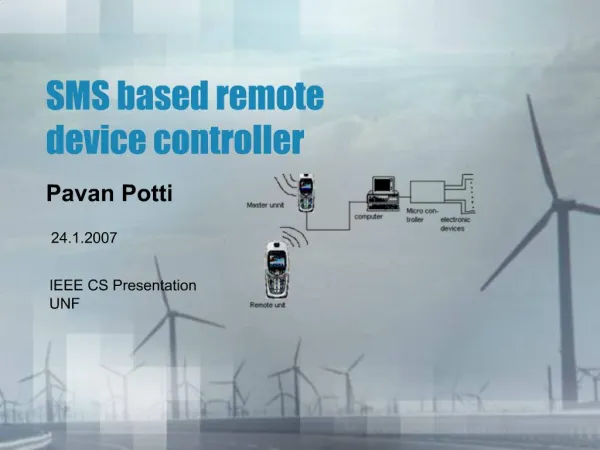
Abstract • Implementation of a system which includes a single Remote Controller capable of controlling several devices in different rooms via Access Points, connected via LAN. • The Remote Controller is implemented on a PDA with Ericsson BT unit and CE OS. • The Access Point is implemented on a PC with Digianswer BT unit. • The device is implemented on a DSP with Ericsson BT unit.
Part A Description Server Printer (Emulated on a DSP with Ericsson BT) LAN Access Point (Digianswer BT) RC (Ericsson BT)
Part A Description (cont.) • The system is capable of controlling any device connected via a piconet to one of the Access Points (connected via LAN.) In Part A we demonstrate a dialog between the RC and the device that are in the same room but in general there is no such restriction. • The constant Data Base is located on the LAN Server. The DB includes two coherent tables – one for all the rooms and one for all the devices - thus allowing the Client flexibility in choice of a device: either from a specific room or a specific type of device.
Part A Description (cont.) • The definition of the data bases in the server Devices DB Rooms DB
Part A Description (cont.) • The AP establishes the piconet by searching for the BT clients and keeps a hash table of established connections (here we assume full correspondence to the DB in the Server.) • As soon as it recognizes the RC client (by a special code) it serves as a bridge for the communication between it and the Server (by launching stream dispatchers.) • The RC client is presented with a menu with which it can choose a device to activate.
Communication with the device Select a room by number Select a device by number Select an action by Number 1) Kitchen … n) RoomN 1) AC … n) DeviceM 1) ON … n) ActionI Main Menu Action info 1) Rooms Menu 2) Devices Menu Performing… Part A Description (cont.) • The menu
Part A Description (cont.) • The device is specified by a pair (roomIP, deviceBD) which are received from the Server by executing SQL inquiries. • As soon as the device is specified, the Server establishes a LAN connection to the appropriate AP by using “roomIP” and sends it “deviceBD”. • The AP checks whether the device is indeed a member of its piconet (by inquiring its hash table) and if so serves as a bridge between the device and the RC (this is called the Request Bridge.) • Additional stream dispatchers are created between the Server and the AP, and between the AP and the device.
Part A Description (cont.) Server Socket • The connections scheme Socket SRSession SRStreamDispatchers AP1 AP2 RFServerSocket RFServerSocket RFBridge RFRequestBridge RFBridge RFRequestBridge (roomIP,deviceBD) Hash table of devices in the piconet Notactivated Hash table of devices in the piconet RFStreamDispatchers Data Base RFStreamDispatchers RFSocket (from the hash table) RFSocket RC Device
Part A Description (cont.) • The classes for the Server and the AP are implemented in JAVA (including HCI implementation written in C and imported through JNI.) • The application for the device is based on the DSK-Bluetooth project written in C. • For the Part A we use the rfBrowser application for the client.
Part A Description (cont.) • The classes handling the access to the data bases SRSessionFactory SRSession Threads SRRoomsWrapper SRDevicesWrapper JDBC_ODBC Bridge JDBC_ODBC Bridge Rooms DB Devices DB
Part A Description (cont.) • The Server classes for dialog SRSessionFactory SRSession ChannelConnector Socket.InputStream Socket.OutputStream SRStreamDispatcher AP2 Side AP1 Side Socket.InputStream Socket.OutputStream
Part A Description (cont.) • The Access Point classes RFBridge/RFRequestBridge RFServerSocket RFSocket.InputStream Socket.OutputStream RFStreamDispatcher/ RFRequestStreamDispatcher LAN Side Blutooth Side Socket.InputStream RFSocket.OutputStream
Part A Description (cont.) • The device accepts connection from the AP and is passive until activated by the client’s request, on which it presents a menu of available actions. • After the RC client specified the desired action, the device acknowledges the request (in the presentation the DSP will toggle one of its LEDs and send an acknowledgement message to the RC client.)
What’s next? • Implementation of a dynamic Data Base which will be updated whenever a connection with device is established or terminated. • Introduction of a new UI for the RC client. • Improvement of the dialog with devices. • System improvements and bug fixings.