Download
1 / 45
570 likes | 1.03k Vues
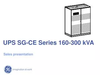
UPS SG-CE Series 160-300 kVA. Sales presentation. PRODUCT HIGHLIGHT. Product portfolio CE Marked, 3x380/400/415V In & Out, 50/60Hz. UPS SG-CE Series 160kVA 144 kW UPS SG-CE Series 200kVA 180kW UPS SG-CE Series 160kVA PurePulse TM 144kW UPS SG-CE Series 200kVA PurePulse TM 180kW

E N D
UPS SG-CE Series 160-300 kVA Sales presentation
Product portfolioCE Marked, 3x380/400/415V In & Out, 50/60Hz UPS SG-CE Series 160kVA 144 kW UPS SG-CE Series 200kVA 180kW UPS SG-CE Series 160kVA PurePulseTM 144kW UPS SG-CE Series 200kVA PurePulseTM 180kW UPS SG-CE Series 250kVA 225kW UPS SG-CE Series 300kVA 270kW UPS SG-CE Series 250kVA PurePulseTM 225kW UPS SG-CE Series 300kVA PurePulseTM 270kW Thyristor rectifier IGBT rectifier 160 – 200 kVA Thyristor rectifier IGBT rectifier 250 – 300 kVA
Double conversion parallelableDesigned for Mission Critical Applications • True On-Line Double Conversion • VFI technology(Voltage and Frequency Independent) • Inverter output transformer for load galvanic separation Bypass supply Static bypass Rectifier Inverter AC DC Load Rectifier supply AC DC Battery bank • Redundant Parallel Architecture™ • RPA™ up to 6 UPS units • Increase system reliability and security • Expanded UPS installed power
High power concentrationNew technology for actual and future trend Reduced footprint • Compact design saving space in installation: - 160-200 kVA: 1350 x 850 x 1900 mm - 250-300 kVA: 1500 x 850 x 1900 mm 1900 850 1350/1500 Full active power available • Full power capability to supply- inductive loads- resistive loads- capacitive loads • Suitable for actual loads applications, e.g. capacitive loads in new datacentre
Performances for actual and future trendHigh efficiency and clean input technologies for modern applications Efficiency 100% High efficiency at any load • High efficiency at full and partial loads for real benefit in operating conditions 94% 80% Efficiency % 60% Typical Operation 40% 20% 0% 10% 25% 50% 75% 100% Load • Clean input UPS by PurePulse™ technology • No input current distortion: THDi = 2% at 100% load 2.5% at 75% load 3% at 50% load • Input power factor: PF=0.99 Total Input Harmonic Distortion 5% 4% 3% THDi 2% 1% 0% 0% 20% 40% 60% 80% 100% Load
Superior output dynamic stiffnessTechnology for actual and future trend Output voltage with non-linear load • No output voltage distortion • Real sinewave output voltage with linear and non-linear loads • Reduced stress for load power supply equipments Voltage variation at 0–100% load step Voltage stability at loads steps • Capability to supply critical loads with high and fast loads steps(pulsating loads) • No oversize required for pulsating loads output voltage current load step 0-100% output voltage current output voltage load step 0-100% output voltage
Typical applicationsDesigned for mission critical applications, with highest levels of protection and reliability Data centers Medical equipment & healthcare facilities Transportation & Infrastructure Call centres Security system and more ...
IEC 62040-3 • CLASSIFICATION
Performance IEC 62040-3 – Level 1Output voltage dependancy ~ • VFI – Voltage & Frequency Independent • Topology: Double conversion/on-line - Load Utility Rectifier Inverter Battery Impedance • VI - Voltage Independent • Topology: UPS-Utility-Parallel operation / Single conversion / Line-interactive Load Utility ~ ~ Converter ~ - Inverter & Charger Battery • VFD – Voltage & Frequency Dependent • Topology: Off-line Utility - - Load ~ ~ ~ - Battery Charger Inverter Switch Level 1: Output voltage dependency from utility (XXX YY ZZZ)
Performance IEC 62040-3 – Level 2Output voltage quality Level 2: Output voltage quality depending on load (XXX YY ZZZ) Sine wave: THD < 8% (IEC 61000-2-2/-4) for all linear and non-linear loads Non-sine wave: THD > 8 % with non-linear load Non-sine wave: out of tolerance of IEC 61000-2-2/ -4 S S X X Y Y Battery operation Normal operation
Performance IEC 62040-3 – Level 3Dynamic output voltage Class 1 Z Z Z Level 3: Dynamic output voltage behaviour (XXX YY ZZZ) Class 2 Class 3 Dynamic load changes with non-linear load (0% – 100%– 0%) Dynamic load changes with linear load (0% – 100% – 0%) Change of operation mode (Utility – battery / Inverter - By-pass)
SG CE classificationExeeding IEC 62040-3 standard requirements Class 1 SG-CE Series SG CE classification: VFI – SSS – 111 VFI Voltage & Frequency Independent Frequency Converter operation available SS Output voltage THD < 8% for all loads THDv < 1.5% linear loads THDv < 3% non-linear loads 111 Class 1 performance Exceeding Class 1 ‘’Best in Class’’ dynamic response: +/- 3% at load step: 0-100%-0 +/- 2% at load step: 0-50%-0
CHARACTERISTICS • & • PERFORMANCES
UPS configurationDouble conversion with inverter output isolation transformer • Double conversion(VFI) technology with output isolation transformer • Automatic bypass for overloads, short circuit and UPS disturbances conditions • Manual bypass for UPS maintenance operations without load interruption • Protection safety devices integrated (back feed protection k6 standard)
Compact designTrue front access for operation and maintenance, saving installation space 1900 850 1350/1500 Reduced footprint • Compact design saving space in installation - 160-200 kVA: 1350 x 850 x 1900 mm- 250-300 kVA: 1500 x 850 x 1900 mm • Easier to handle in narrow space True front access • Installation against a wall • More space available for other equipments Reduced weigh • Easier to handle into installation site(e.g. transportation though floors by lift) • Reduced installation time and cost UPS 850 1.600 1.350 Footprint SG 200kVA UPS : 1.350 x 0.850 = 1.15 sqm Operational : 1.350 x 1.600 = 2.16 sqm
Highest UPS output power capabilityCapability to supply Inductive, Resistive and Capacitive loads • Full range power capability • Designed to supply real power for any type of application - inductive loads- resistive loads- capacitive loads • No over-sizing required to supply resistive and capacitive loads • Suitable for modern power supply application with unit or capacitive power factor (e.g. new servers generation), crest factor up to 3:1 E.g. SG 300kVA load capabilities: Inductive load PF=0.9 270 kW / 300 kVA Resistive load PF=1 270 kW / 270 kVA Capacitive load PF=0.9 270 kW / 300 kVA
Input rectifier performancesWide input window to preserve battery autonomy and lifetime +10% 50 Hz -10% -15% +15% 400V Input window Wide input voltage and frequency windows • Limited use of battery • Preserve battery autonomy for real input mains failures • Increase battery lifetime Soft start • Rectifier can be activated gradually, controlling the input current • Preventing instable situation for GenSet • Avoids false trip of upfront protection devices • Sequential softstart for parallel UPS Input frequency Input voltage Soft start • UPS input current UPS 1 UPS 2 • 100% • 0% • time
Backfeed protection IEC 62040-1 : ……“For fixed installation UPS, backfeed protection may be provided internally or externally to the UPS in the a.c. input line” Backfeed contactor static bypass Input mains Rectifier Inverter AC Load DC DC AC Battery bank Standard feature inside UPS cabinet • No additional cost required • No addition installation required Fully compliant with IEC 62040-1 • Compliance to UPS installation safety requirements Safer operating condition • Safer operation for end users and service engineers preventing feedback to the mains from the inverter in case of mains failure and a fault in the bypass circuit
IGBT technology for clean inputPure Pulse configuration for highest input performances Total Input Harmonic Distortion 5% 4% 3% THDi 2% 1% 0% 0% 20% 40% 60% 80% 100% Load PurePulse technology for IGBT rectifier UPS input performances • Total Current Harmonic Distortion THDi=2% • UPS input power factor: 0.99 Constant behavior at all loads • Negligible harmonics contents at full and partial loads Benefit on input mains • Saving in the sizing of upfront equipments e.g. GenSet, cablings, circuit breakers, … • No disturbances to nearby equipment • Saving cost due to additional filters
Perfect integration with GenSetNoGenSet oversizing required GenSet integration • Compatible with GenSet design • Saving GenSet size(suggested GenSet vs. UPS ratio ~ 1.1*) • Reducing GenSet installation space • Saving GenSet investment GenSet system integration • GenSet integration via Customer Interface (dedicated auxiliary contact) • Programmable functions based on GenSet working condition (Gen on/off) * Pure Pulse configuration and GenSet able to manage large load steps Example Load 300 kVA; PF=0.8; 240 kW UPS SG 300 kVA Pure Pulse; input PF = 0.99 GenSet data reactance subtr. X“d=12% GenSet size min. size required 332 kVA GenSet/UPS = 332/300 = 1.1
Superior Battery ManagementSafe and protected battery management to preserve investment and UPS reliability Flexible applications • Different battery technologies applicable: PB sealed (VRLA) - PB vented – NiCd • Wide autonomy range (from few minutes to some hours) User friendly information • Prediction of true back-up time, based on load status • Alarm for “stop operation” to prevent any unknown shut-down Monitoring and control • Battery test (programmable or manual) ; preserve UPS system reliability • Battery earth fault detection; safer operation for service engineer & end user Voltage temperature compensation
No output voltage distortionBest in class inoutput dynamic stiffness Output voltage with non-linear load Output voltage with linear + non-linear load • No output voltage distortion with linear and non-linear loads • Voltage distortion - linear loads: THDv < 1.5% - non-linear loads: THDv < 3% Enhanced customer productivity • Improved quality of application, reducing stress for loads supplied • Increased uptime and MTBF of customer • Reduced service intervention (e.g. medical applications: ~60% labor hour & spare parts reduction) output voltage current output voltage current
Output Dynamic StiffnessBest in class inoutput dynamic stiffness Voltage variation at 0–100% load step load step 0-100% output voltage Medical scanner - dynamic current absorbtion • Best in class in output voltage variation with load steps: • Static : < + 1% • Dynamic at load steps 0-50-0% : < + 2% • Dynamic at load steps 0-100-0% : < + 3% Enhanced customer unit productivity • Improved quality of application (i.e. medical images) • Capability to supply critical loads with high and fast loads steps (pulsating loads) • Increased uptime and MTBF of customer • Reduced service intervention 1 ms
High Efficiency at all loadsReduced customer operation costs and cost saving in air conditioning design SG CE Thyristors rectifier – Efficiency* 100% 94% 80% Efficiency % 60% Typical Operation 40% 20% 0% 10% 25% 50% 75% 100% Load High efficiency performances at any load • High efficiency at full and partial loads for real benefit in operating conditions Energy cost saving • Reduced cost of customer equipment operation at all loads Air conditioning cost saving • Reducing size and cost of air condition system • Reducing consumption and related operating cost * SG CE PurePulse (IGBT rectifier) 1% less
Super Eco Mode - functionalityImproving UPS efficiency Bypass supply Static bypass Rectifier Inverter AC DC Load Rectifier supply AC DC Battery bank Bypass supply Static bypass Rectifier Inverter Transf. AC DC Load Rectifier supply AC DC Battery bank Normal mode Normal mode • The output voltage is newly generated, independently from the input voltage • Heat losses are present in rectifier and inverter Super Eco Mode • Load is supplied via the bypass • UPS rectifier keeps the battery charged • UPS inverter switched off(no heat losses) Super Eco Mode
Super Eco Mode - benefitHigh efficiency, preserving protection to critical load < 2ms • High efficiency: 98% • prevents heat losses • saving customer utility bill • Fast transfer time to inverter: <2 ms • Guaranteed safe energy for the application • Configurable according to load requirement • Adjustable bypass supply tolerance - voltage: +/- 10% (adjustable) - frequency: +/- 5% (adjustable) Bypass on/off Output voltage Inverter current Inverter control
Reduntant Parallel ArchitectureTrue redundancy with no single point of failure Input mains rectifier bypass rectifier bypass AC AC DC DC battery battery DC DC AC AC critical load • Modular design • Future system expansion • Saving investment True redundancy • No single point of failure • Decentralized bypass • Distributed parallel management system Increased system reliability • Safe and reliable power supply for “mission critical applications” • Increase productivity • True redundancy with no single point of failure
Reduntant Parallel ArchitectureIncrease system reliability for Mission Critical Applications redundantcommunicationbuses Configurable up to 6 units in parallel • Future expansion • Safe and reliable power supply • Redundant Communication Bus Easy to install and maintain • Easy system upgrade/downgrade • Maintenance operation withoutload interruption utility supply critical load
EMC - Electro Magnetic Compatibility immunityIEC 62040-2 standard defines the limits of maximum allowable levels of emission of electromagnetic disturbances for UPS systems Emission • Any electronic devices emits electromagnetic disturbances - radio frequency waves - through: • cables (conducted emissions) • air (radiated emissions) • Immunity • All electronic equipment is sensitive for electromagnetic waves.These waves can disturb the functions of these equipments • Electro Magnetic Compatibility • Disturbances tolerance among different types of equipment when running in the same environment.
EMC Category C2 (Class A), optional feature*Compensation of radio-frequency emission to avoid distrurmabces on nearby equipments No interference with other equipments • Avoid any interferences with critical applications sensitive to radio frequency emission (e.g. telecom, broadcasting, …) • No additional investment required for EMC investigation. Protected unit quality enhancement • Increased quality and productivity (e.g. Image quality in medical application) *Additional EMC cabinet required
Designed for serviceabilitySaving time and cost in service Easy maintenance interventention • Reducing time and cost on maintenance intervention • Reducing down-time, increasing availability
Fan failure detectionVentilation monitoring for highest reliability fan failure Ventilation monitoring • Alert before overheating occurs • Continuos monitoring of cooling system • Repairing time reduction • Fault level decreasing detection alarm
POWER QUALITY • SYSTEMS
Power Quality SystemsIntegretion with other Power Quality euipments for Mission Critical Applications UPS: Uninterruptible Power Supply ISM: Intelligent Synchronization Module STS: Static Transfer Switch Battery-B Battery-A UPS-B ISM UPS-A Input mains STS-B Input mains STS-A Load-B Load-A
Customer interfaceEasy integration with Building Management System (BMS) UPS supervision capability • 1x RS232 Serial Communication Port • 6 programmable potential free alarm contacts: - D plug - Terminals blocks • 1x Emergency Power OFF contact • 1x Gen-ON Input contact • 1x Control Input contact Additional interface: • SNMP Interface Card(10/100Mbps auto-select) • MODBUS RTU Interface (RS232 or RS485) Customer interface
IRIS - Intelligent Remote Information SystemRemote monitoring and diagnostics solution • SNMP/Modem/GPRS topologies available • Flexible, safe and customer-friendly solution for remote monitoring • Secure communication via: • e-mail, SMS, fax • GPRS • Web/PDA Data Acquisition Communication Medium IRIS Infrastructure User Interface


![300-160 Exam Dumps - Prepare 300-160 Dumps PDF [2018]](https://cdn4.slideserve.com/7925965/cisco-300-160-exam-dt.jpg)
![Cisco 300-160 Dumps Question - Data Networking [300-160] Exam Question](https://cdn4.slideserve.com/7938520/questions-answers-pdf-dt.jpg)