Download
1 / 35
350 likes | 370 Vues
Explore the behavior of water droplets in fuel cell diffusion media, focusing on droplet mobility and coalescence for performance enhancement. Mathematical modeling and simulations are utilized to analyze factors affecting droplet dynamics and growth.

E N D
Mobility and Coalescence of Water Droplet Formed in Fuel Cells
Overview • Introduction • Objectives • Mathematical Modeling • Sample Simulations
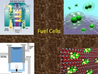
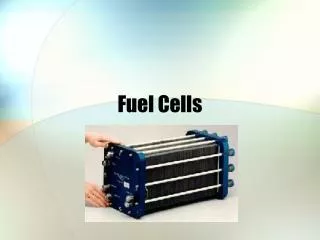
Introduction • A unit cell of PEMFC is composed of a membrane electrode assembly, two diffusion media, and bipolar plates. • The diffusion medium needs to be optimized to enhance the cell performance. • In cathode diffusion medium, the product water flows towards the channel through gas-phase diffusion or liquid-phase motion. Porous Cathode H2O H2 O2 H+ Porous Anode
At high current densities, the liquid flow rate increases due to the increased condensation, and when the channel is at the local vapor saturation condition, liquid water flows out of diffusion medium and surface droplet are formed.
Fiber Screens Stacked fiber screens, and the same exposed to water-vapor saturated atmosphere.
Objective • Characterization of the mobility of micro-drops in the diffusion medium. • Growth of the micro drops through coalescence. • Consider effect of: • Initial droplet number density; • Initial droplet size; • Vapor diffusion rates; • Rate of droplet onset; • Growth rate of drops; • Surface contact angles; • Thickness of the membrane.
Mathematical Model • Basic assumptions • Laminar flow ; incompressible and Newtonian fluid • Governing equations • Continuity • Momentum • Free-surface tracking • Modified flow equations in presence of solid walls • Finite volume method ; structured mesh ; Youngs algorithm ; volume fraction for walls
Energy Equation- Enthalpy Method • Original Energy Equation • Final Energy Equation
liquid .48 0 0 .10 .38 0 .25 .87 1 1 .91 1 1 1 .12 Free Surface Tracking • Step 1. Specify liquid domain using VOF method • Define a function • Represent actual liquid domain by corresponding values Actual liquid region Volume of Fluid representation
Liquid 0.2 0.8 1 0 0.05 0.7 0 0 0.1 Wall Modeling Solid Walls • Step 1: Define a Volume Fraction • Step 2: Use instead of a stair-step model • Step 3: Modify fluid flow equations
Modified Fluid Equations • Continuity, Momentum and VOF Equations
Sample Simulations Impaction of a water Drop on a fiber Droplet diameter: 2 mm two perpendicular tubes (0.5 mm) no offset 3.18 mm tube; 1 m/s offset 1.55 mm
Code Validation • Droplet : 2 mm, 1 m/s; Tube: 3.18 mm (0.125 in); Offset: 1.55 mm
Code validation (continued) • Droplet : 2 mm, 1 m/s; Tube: 3.18 mm (0.125 in); Offset: 1.55 mm
Droplet flow through a modeled Porous Medium • Radial Capillary • A staggered array of perforated plates
Draw back and coalescence:Drop Spacing 42 m ; • Droplets coalesce Contact Angle 45o Contact Angle 120o
Drop Spacing 44 m ; Contact Angle 120o • Droplets do not coalesce
Droplet Collisions • Head- On Collisions • Permanent Coalescence • Reflexive Separation • Off-axis Collisions • Permanent Coalescence • Stretching Separation then Permanent Coalescence • Stretching Separation • Tearing or or
Droplet Coalescence Drop Collisions: Experiments vs. Simulations Experimental Numerical
Off-Axis CollisionsTearing (Water, We=56, Re=2392, X=0.73 and =0.5)
Summary • Our 3D free surface code can simulate the detailes of the droplet dynamics in porous systems.
Continuity and Momentum • Two-step time discretization of momentum equation: • Step (i): evaluate convective, viscous and surface tension effects explicitly • Step (ii): combine with continuity equation to obtain the Poisson pressure equation:
0 .05 .20 u .10 .87 1 Free Surface Tracking • Step 2. Use function to advect the free surface to a new location at each time step • Step 3. Reconstruct the free surface shape at the new location using Youngs algorithm Obtain normal and use values of : get free surface cutting planes
Youngs’ 3D-VOF Interfaces - piecewise “planes” Interface plane is fitted within a single cell Interface slope and fluid position are determined from inspection of neighboring cells Pentagonal Section
Youngs’ 3D - Cases Triangle Quadrilateral - A Quadrilateral - B Pentagon Hexagon
Youngs’ VOF Implementation • Surface Reconstruction • Using f-field determined cell “normal” (i.e. ) • Determine “case” using normal • Position plane with known slope based upon volume fraction • Compute plane area and vertices • Fluid Advection, • Compute flux across cell side (case dependent) • Operator Split (i.e. do for x, y and z sweeps)
General Solution Procedure • Specify initial surface geometry and velocities • Begin Cycle, increment time and repeat 2-6 until done • Explicitly update convective terms viscous terms surface tension terms • Implicitly calculate using ICCG Method • Update with and apply BCs • Advect f-field using Youngs VOF and re-apply BCs
d s V r V r Nondimensional Parameters Impact Parameter V Weber Number s b Relative Velocity Size Ratio d V l X (X=0) (X>0)
0 1 2 3 4 5 6 7 8 9 10 12 13 11 14 15 16 17 18 19 20 21 22 24 23 Head-on CollisionsSeparation (Water, We=58, Re=1127)
0 1 2 3 4 5 6 7 8 9 10 11 12 13 14 15 16 17 18 19 20 Off-axis CollisionsCoalescence (Water, We=25, Re=740, X=0.7)