Hidden Line Removal
500 likes | 1.31k Vues
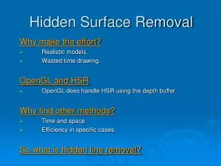
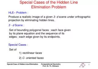
Hidden Line Removal. Adopted from U Strathclyde’s course page. Introduction. Depth cueing Surfaces Vectors/normals Hidden face culling Convex/concave solids. Perspective Confusion. Hidden Line Removal. (show demo – basic3d wireframe surface). Hidden Line Removal. No one best algorithm

Hidden Line Removal
E N D
Presentation Transcript
Hidden Line Removal Adopted from U Strathclyde’s course page
Introduction • Depth cueing • Surfaces • Vectors/normals • Hidden face culling • Convex/concave solids
Hidden Line Removal (show demo – basic3d wireframe surface)
Hidden Line Removal • No one best algorithm • Look at a simple approach for convex solids • based upon working out which way a surface is pointing relative to the viewer. convex concave
Based on surfaces not lines • Need a Surface data structure • WireframeSurface • made up of lines
Flat surfaces • Key requirement of our surfaces is that they are FLAT. • Easiest way to ensure this is by using only three points to define the surface…. • (any triangle MUST be flat - think about it) • …but as long as you promise not to do anything that will bend a flat surface, we can allow them to be defined by as many points as you like. • Single sided
Which way does a surface point? • Vector mathematics defines the concept of a surface’s normal vector. • A surface’s normal vector is simply an arrow that is perpendicular to that surface (i.e. it sticks straight out)
Determining visibility Consider the six faces of a cube and their normal vectors Vectors N1 and N2 are are the normals to surfaces 1 and 2 respectively. Vector L points from surface 1 to the viewpoint. It can be seen that surface 1 is visible to the viewer whilst surface 2 cannot be seen from that position.
Determining visibility • Mathematically, a surface is visible from the position given by L if: • Where q is the angle between L and N. • Equivalently,
Determining visibility • Fortunately we can calculate cos q from the direction of L (lx,ly,lz) and N (nx,ny,nz) • This is due to the well known result in vector mathematics - the dot product (or the scalar product) whereby:
Determining visibility • Alternatively: • Where L and N are unit vectors (i.e of length 1)
How do we work out L.N? • At this point we know: • we need to calculate cos q • Values for lx,ly,lz • The only things we are missing are nx,ny,nz
Calculating the normal vector • If you multiply any two vectors using the vector product, the result is another vector that is perpendicular to the plane (i.e normal) which contained the two original vectors.
IMPORTANT • We need to adopt the convention that the calculated normal vector points away from the observer when the angle between the two initial vectors is measured in an clockwise direction. • Failure to do this will lead to MAJOR confusion when you try and implement this • Believe me, I know.
Calculating the normal • Where to find two vectors that we can multiply? • Answer: we can manufacture them artificially from the points that define the plane we want the normal of
Calculating the normal • By subtracting the coordinates of consecutive points we can form vectors which a guaranteed to lie in the plane of the surface under consideration.
Calculating the normal • We define the vectors to be anti-clockwise, when viewing the surface from the interior • (imagine the surface is part of a cube and your looking at it from INSIDE the cube). • Following the anticlockwise convention mentioned above we have produced what is known as an outward normal.
IMPORTANT • An important consequence of this is that when you define the points that define a surface in a program, you MUST add them in anti-clockwise order
Calculating the normal This is a definition of the vector product
Visibility • At this point we know: • we need to calculate cos q • Values for lx,ly,lz • values for nx,ny,nz
Visibility If then draw the surface else don’t! (or draw dashes)
Making it easier • Actually, in certain cases we can simplify things a little. If the viewpoint lies somewhere on the negative side of z-axis, as it did when we first set up the projection transformations (i.e without any viewpoint transformations) we can forget about L and cos q • All we really need to know is whether or not the normal points into the screen or out of it, i.e. is nz positive or negative? In that case, all we need to do is calculate nz and test it
An alternative approach • Consider where the extension of the surface cuts the z-axis
More complex shapes Concave objects Multiple objects
More complex shapes • In these cases, each surface must be considered individually. Two different types of approach are possible: • Object space algorithms - examine each face in space to determine it visibility • Image space algorithms - at each screen pixel position, determine which face element is visible. • Approximately, the relative efficiency of an image space algorithm increases with the complexity of the scene being represented, but often the drawing can be simplified for convex objects by removing surfaces which are invisible even for a single object.
The z-buffer (or painter’s) algorithm • based upon sorting the surfaces by their z-coordinates. The algorithm can be summarised thus: • Sort the surfaces into order of increasing depth. Define the maximum z value of the surface and the z-extent. • resolve any depth ambiguities • draw all the surfaces starting with the largest z-value
Ambiguities • Ambiguities arise when the z-extents of two surfaces overlap. <two books demo>
Resolving Ambiguities • An algorithm exists for ambiguity resolution • Where two shapes P and Q have overlapping z-extents, perform the following 5 tests (in sequence of increasing complexity). • If any test fails, draw P first.
Is P not completely on the side of Q further from the viewer?
If all tests are passed • … then reverse P and Q in the list of surfaces sorted by Zmax • set a flag to say that the test has been perfomed once. • The flag is necessary for the case of intersecting planes. • If the tests are all passed a second time, then it is necessary to split the surfaces and repeat the algorithm on the 4 surfaces
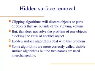
Summary • Need for depth cues and hidden line removal • Using surfaces rather than lines • Calculating which way a surface is facing (surface normal) • Base a decision on visibility on normal vector and observer vector
References • http://local.cis.strath.ac.uk/teaching/ug/classes/52.359if/