Hidden Line Removal Using Vector Algebra
210 likes | 282 Vues
Explore the application of vector algebra to remove hidden lines from wire-frame models by focusing on convex objects, face planes, angles, vectors, and dot products. Learn about data-set formats, normals, cross-products, and implementing bitblit techniques.

Hidden Line Removal Using Vector Algebra
E N D
Presentation Transcript
Hidden Line Removal Applying vector algebra to the problem of removing hidden lines from wire-frame models
Convex objects • We first focus on modeling convex objects • One “outward face” cannot hide another • So visible faces can be drawn in any order • Examples: barn, cube, and dodecahedron
A non-convex object part of this face is hidden by that face eye of viewer
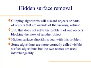
2D Polygons in 3D space • A polygon is a 2-dimensional figure • Its edges and corner-points are coplanar • It’s a bounded region of an infinite plane • Any plane in 3-space can be described by an first-degree (linear) algebraic equation: ax + by + cz = d • Alternatively, using vector algebra, a plane can be described using a reference-point Q and a direction-vector N = (a, b, c), as: N • QP = 0
Face-Planes of solid objects • Any plane surface has two sides • When a plane is a surface of a solid object it has an “inside” surface and an “outside” surface (a viewer sees the “outside” one) front back viewer
Angles and cosines • An angle of 90-degrees is a “right” angle • Angles less than 90-degrees are “acute” • And angles over 90-degrees are “obtuse” obtuse angle right angle acute angle cosine < 0 cosine > 0 cosine = 0
Vectors and dot-products • Vectors u = (ux, uy, uz) and v = (vx, vy, vz) have a dot-product: u•v = ux vx + uy vy + uz vz • A vector’s length ║u║ equals sqrt( u•u ) • A dot-product is related to the cosine of the angle θ between the two vectors: u•v = ║u║║v║cosine(θ) • So sign of dot-product tells angle’s type
Visibility of face-planes N = outward pointing normal vector N D θ D•N > 0 (acute angle θ) outer surface is visible D = direction vector (from plane toward viewer’s eye)
“Hidden” face-plane N = outward pointing normal vector N θ D D•N < 0 (obtuse angle θ) outer surface is hidden D = direction vector (from plane toward viewer’s eye)
Format of model’s data-set • Added data needed to describe our model • Number and Location of vertices as before • Edge-list is no longer needed (zero edges) • Face-list is the new information to be add • Each face is a polygon: number of sides, list of vertices in counter-clockwise order (as viewed from the outside of the model), and the face-color to be used for the face
Example data-set: cube 7 0 Face-List (6 faces) 3 4 4-sided: 0, 1, 2, 3 (blue) 4-sided: 1, 0, 7, 6 (green) 4-sided: 2, 5, 4, 3 (cyan) 4-sided: 4, 5, 6, 7 (red) 4-sided: 6, 5, 2, 1 (magenta) 6 1 5 2 The vertices of each face should be listed in counterclockwise order (an seen from the outside of the cube)
Why counterclockwise order? • We need to compute the outward-pointing “normal” vector for each polygonal face (to determine if that outward face is visible) • That normal vector is easily computed (as a vector cross-product) if the vertices are listed in counterclockwise order
Recall the cross-product: u×v • If u = ( ux, uy, uz ) and v = ( vx, vy, vz ), then w = u×v is given by these formulas: wx = uyvz – uzvy wy = uzvx – uxvz wz = uxvy – uyvx • Significance: cross-product w makes a 90-degree angle with both u and v (so it’s normal to a plane containing u and v)
Three consecutive vertices p×q p = v1 – v0 q = v2 – v1 V1 q p V2 V0 p×q will be the outward-pointing normal vector (if v0, v1, v2 occurred in counterclockwise order)
Remembering u x v • Here’s a “trick” students use to remember the formula for computing a cross-product • It’s based on the “cofactor expansion” rule for 3x3 determinants: a b c e f d f d e d e f = a - b + c g h i h i g i g h
Applying this “trick” i = (1,0,0), j = (0,1,0), k = (0,0,1) u = (ux,uy,uz) v = (vx,vy,vz) i j k u x v = ux uy uz vx vy vz = ( uyvz – uzvy, uzvx – uxvz, uxvy – uyvx )
Demo program • Our ‘filldemo.cpp’ application reads in the data for a 3D model, determines which of its polygonal faces are visible to a viewer, fills each visible face in its specified color, and then draws the edges of visible faces • Datasets: plato.dat, redbarn.dat, plane.dat • Also two models for a non-convex object: corner1.dat and corner2.dat (same object)
The ‘bitblit’ technique • Our ‘filldemo’ program achieves its smooth animation, not with ‘page-flipping’, but with the so-called ‘bitblit’ method • This approach has the advantage that it avoids dependency on Radeon hardware (e.g., using the CRTC_START register)
How ‘bitblit’ is used CRTC_START (never gets changed) Visible page (page 0) Drawing page (page 1) All the drawing is done to page 1 (which never gets displayed) Then after an image has is fully drawn, it is rapidly copied to page 0 (‘bitblit’) VRAM
In-class exercises • Try to create the data-sets for some “more interesting” 3D objects, (by writing a C++ program to generate the object’s vertices and the face-lists) • Example: An octagonal prism • Divide a circle into eight equal-size angles • Use sine and cosine to locate upper vertices • Use sine and cosine to locate lower vertices • Use number-patterns to generate its ten face-planes