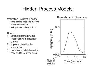
The Rendering Process Hidden Line and Hidden Surface Removal (HLHSR)
1.12k likes | 1.36k Vues
Introduction to 2D and 3D Computer Graphics. The Rendering Process Hidden Line and Hidden Surface Removal (HLHSR). Mastering 2D & 3D Graphics. Discuss HLHSR Techniques General Concepts Trival Rejection Backface Culling Depth Sorting Z Buffering . The Rendering Process

The Rendering Process Hidden Line and Hidden Surface Removal (HLHSR)
E N D
Presentation Transcript
Introduction to 2D and 3D Computer Graphics The Rendering Process Hidden Line and Hidden Surface Removal (HLHSR)
Mastering 2D & 3D Graphics • Discuss HLHSR Techniques • General Concepts • Trival Rejection • Backface Culling • Depth Sorting • Z Buffering
The Rendering Process Hidden Line and Hidden Surface Removal Introduction • Many 3D objects have surfaces that are planar polygons... . • ..for example, cubes, pyramids, prisms, etc. • Many more complex objects - are often built from these • Curved surfaces can often be approximated by planar polyhedrons joined together...simulating the actual surface
The Rendering Process Hidden Line and Hidden Surface Removal Introduction • The curvature of a cylinder can be represented by many long narrow rectangles • The advantage of using planar polygons to represent your objects is... • that the display algorithms can take advantage of this and produce the objects by simply drawing the edges for wireframes or by simply filling the polygons • But...objects may appear ambiguous because edges may be shown that wouldn't be seen in real life!
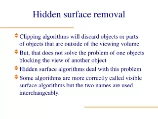
The Rendering Process Hidden Line and Hidden Surface Removal Introduction • HLHSR is the process of determining which lines or surfaces of objects are visible, either from the center of projection for perspective projections or along the direction of projection for parallel projections • Allows only the visible lines or surfaces to be displayed
The Rendering Process Hidden Line and Hidden Surface Removal Introduction • Provides both image-precision and object-precision methods • Image-precision is performed at the resolution of the device and determines the visibility of each pixel; it is performed AFTER rasterization • Object-precision is performed in NPC space (after viewing); it is followed by operations to map to device coordinates and physically render the picture
The Rendering Process Hidden Line and Hidden Surface Removal Introduction • Image-precision... • ...is a simple approach ...for each pixel in the picture: • (a) determines the object closest to the viewer that is pierced by the projector through the pixel, and • (b) draws the pixel in the appropriate color
The Rendering Process Hidden Line and Hidden Surface Removal Introduction • Object-precision... • ...compares objects directly with one another ...for each object in the picture: • (a) determines those parts of the object whose view is unobstructed by other parts of it or any other object • (b) draws those parts in the appropriate color
The Rendering Process Hidden Line and Hidden Surface Removal Introduction • Image-precision...and...object-precision... • ...require a number of costly operations such as: • ...determining whether or not a projector and an object intersect and where they intersect • ...determining the intersection for multiple projections/objects • ...for intersections, determining which object is closest to the viewer and therefore visible
The Rendering Process Hidden Line and Hidden Surface Removal Introduction • HLR/HSR algorithms can be optimized using techniques of... . • ..coherence • ...depth comparisons • ...trivial rejection: pruning • ...backface culling • Common HLR/HSR algorithms include... • ...backface culling ...depth-sorting • ...Z-buffering
The Rendering Process Hidden Line and Hidden Surface Removal Optimized Techniques • Coherence... • ...is the degree to which parts of a projection of an object have similar features • ...takes advantage of properties of objects that vary smoothly from one part to another • ...allows calculations to be reused without modification or with incremental changes more efficiently than recalculating the information from scratch
The Rendering Process Hidden Line and Hidden Surface Removal Optimized Techniques • Coherence includes... • ...object coherence: takes advantage of one object's location over another's and only compares objects to see if they are completely separate • ...face coherence: since surface properties typically vary smoothly across a face, computations for one part of a face can be modified incrementally to apply to adjacent parts
The Rendering Process Hidden Line and Hidden Surface Removal Optimized Techniques • Coherence includes... . • ...edge coherence: an edge may change visibility only where it crosses behind a visible edge or penetrates a face • ...depth coherence: adjacent parts of the same surface are typically close in depth; once the depth is calculated, the depth of the rest of the surface can be calculated using simple difference equations
The Rendering Process Hidden Line and Hidden Surface Removal Optimized Techniques • Depth comparisons... • ...determine if two or more points obscure one another (i.e., if two or more points lie on the same projector) • ...determine which point is closer when points have the same projector • projectors • • (x2,y2,z2) center of projection (x1,y1,z1)
The Rendering Process Hidden Line and Hidden Surface Removal Optimized Techniques • If two points have the same projector, then the closer one obscures the other • Remember, HLR/HSR occurs in 3D space prior to mapping to 2D, since depth info is lost in 2D... • ...it also occurs in NPC space after viewing, which simplifies the comparisons for parallel and perspective projections, making projectors parallel to the z axis with the center of projection at infinity on the positive z axis (points are obscured if x1=x2 and y1=y2)
The Rendering Process Hidden Line and Hidden Surface Removal Optimized Techniques • Trivial rejection...called pruning • ...is a simple way to avoid unnecessary comparisons • ...again uses the concept that viewing (i.e., perspective) has already been applied • ...requires simple orthographic projections of objects onto the XY plane by ignoring the z values • ...if extents do not overlap, projections do not need to be tested for overlap with one another ...if extents do overlap, projectors must be tested for overlap...however this is not a guarantee that overlap occurs
The Rendering Process Hidden Line and Hidden Surface Removal Optimized Techniques • Trivial rejection...called pruning Y Z Examples where extents overlap & projectors are tested for overlap; remember there is no guarantee! X Two objects with their projections onto the XY plane and the extents surrounding the projections
The Rendering Process Hidden Line and Hidden Surface Removal Optimized Techniques • Trivial rejection...using bounding volumes... • ...uses a bounding volume around each entire object instead of using XY projections • Trivial rejection...using a single dimension... • ...selects a single dimension to determine if overlap occurs • ...for example, could determine if objects overlap in z
The Rendering Process Hidden Line and Hidden Surface Removal Optimized Techniques • Trivial rejection... Zmax Y Zmin Z Using one dimensional extends to determine if objects overlap X Two objects with their bounding volumes
The Rendering Process Hidden Line and Hidden Surface Removal Optimized Techniques • Backface culling...an object-precision technique... • ...is useful for objects approximated by polyhedra • ...eliminates backfacing polygons (i.e., polygonal faces whose surface normals point away from the observer and whose visibility is completely blocked by other closer polygons) • ...since viewing has already occurred, the direction of projection is (0,0,-1) which means surface normals with negative z coordinates are backfacing
The Rendering Process Hidden Line and Hidden Surface Removal Optimized Techniques • Backface culling...an object-precision technique... • ...for a single convex polyhedra, backface culling is the only HLR/HSR algorithm needed! X Backfacing polygons are eliminated but frontfacing polygons are retained Z
The Rendering Process Hidden Line and Hidden Surface Removal Optimized Techniques
The Rendering Process Hidden Line and Hidden Surface Removal Back Face Removal • To perform HLHSR requires... • ...considerable computation to distinguish between visible and invisible edges of an object • Instead, it is easier to find those planar polygons that are not to be shown, rather than to find their edges!
The Rendering Process Hidden Line and Hidden Surface Removal Back Face Removal • Backface culling... • ...is particularly useful for polygon mesh objects • ...removes a significant portion of the hidden lines from a wireframe display • ...removes ALL hidden lines from convex objects • ...is a low cost operation ...will only remove about 50% of surfaces when there are multiple overlapping objects
The Rendering Process Hidden Line and Hidden Surface Removal Back Face Removal
The Rendering Process Hidden Line and Hidden Surface Removal Back Face Removal • These algorithms assume... • ...we are describing our objects as polygon meshes • Remember a polygon mesh... • ...contains many planar surfaces and straight edges • ...which shouldn't be thought of as simply unrelated sets of polygons ...instead, it consists of a mesh of polygons that are adjacent
The Rendering Process Hidden Line and Hidden Surface Removal Back Face Removal • With a polygon mesh... • ...we should record the sequence of vertices or edges that compose the individual polygons • A polygon mesh should allow us to... • ...identify a specific polygon in the mesh ...identify all edges belonging to a polygon ...identify those polygons that share an edge ...identify the vertices of an edge ...change the mesh ...display the mesh
The Rendering Process Hidden Line and Hidden Surface Removal Back Face Removal • An explicit polygon mesh... • ...stores each vertex in a "vertex table" ...defines a polygon as a sequence of vertices ...which can be realized by defining the polygons as linked lists of pointers into the vertex list V2 V4 polygon 1: V1 V3 0 V2 polygon 2 polygon 2: V3 V4 0 V2 polygon 1 V1 V3
The Rendering Process Hidden Line and Hidden Surface Removal Back Face Removal • •The advantages of this approach is... • ...it requires the least amount of storage ...and easily allows for the mesh to be changed • (i.e., to change one vertex - we only have to change its coordinates in the vertex list)
The Rendering Process Hidden Line and Hidden Surface Removal Back Face Removal • An explicit edge mesh... • ...is an alternative representation which overcomes the disadvantages of an explicit polygon mesh • Table of vertices:each vertex is stored once • Linked list of edges:where an edge is connected by two vertices ... where every edge has a pair of pointers to the vertex table, a pointer into the polygon list and a counter showing the # of polygons that share edge • List of polygons: a linked list of pointers into the edge list which access (in the correct order) all of the edges that compose that particular polygon
The Rendering Process Hidden Line and Hidden Surface Removal Back Face Removal Polygon List E4 V2 V4 polygon 1: E1 E3 0 E2 E1 polygon 2 polygon 2: E2 E5 0 E5 E4 polygon 1 V1 E2 E3 List of Edges V3 Edge 1: V1 V2 1 P1 0 V2 V3 2 P2 0 P1 Edge 2: Edge 3: V3 V1 1 P1 0 Edge 4: V2 V4 1 P2 0 Edge 5: V4 V3 1 P2 0
The Rendering Process Hidden Line and Hidden Surface Removal • Backface culling... • ...uses a viewpoint (usually the center of projection) • ...determines whether or not a polygon is visible from the viewpoint • ...determines visibility by calculating the angle between the polygon surface normal and the line-of-sight vector • ...visibility=Normal•Viewpoint
The Rendering Process Hidden Line and Hidden Surface Removal Viewpoint • Line-of-sight vectors <90Þ Visible >90Þ Invisible >90Þ Invisible Surface Normal
The Rendering Process Hidden Line and Hidden Surface Removal • Backface culling... • ...calculates the surface normal from three noncollinear vertices • ...these define two vectors contained in the plane of the surface • ...takes the cross-product which gives the surface normal • ...if all three points occur in a counterclockwise direction around the surface, when you look from the outside, the normal will point outwards Vertex 1 • Vertex 3 • Surface Normal • Vertex 2
The Rendering Process Backface Culling • Another way to look at these calculations... • ...is that if you have a point that lies on the same side of the plane (the positive side) as your viewpoint • ...then, the angle between the vector created from this viewpoint to the plane and the surface normal must be less than š/2 • ...which means: (where Ž is the angle between the vectors)
The Rendering Process Backface Culling • Surface Normal • Viewpoint Vector = |Surface Normal| * |Viewpoint Vector| * cos Ž • will result in a value >0 • This tells us that a positive result will be calculated for every point on the side of a plane that is within view of our viewpoint... • ...and therefore, that a negative result will be given for all planes that cannot be seen from the viewpoint!
The Rendering Process Backface Culling • Let's step through an example... • ...the first step is to apply the viewing transformation • ...then calculate the surface normal ...to do this, a common technique is to use three points on that plane • So, let's start our example, with 3 points P1, P2, and P3 with coordinates (x1,y1,z1), (x2,y2,z2), and (x3,y3,z3) • ...these three points are noncollinear!
The Rendering Process Backface Culling • Note that the direction of projection is (0,0,-1)... • ...in this case the dot product test reduces to checking the z-coordinate of the surface normal • ...if the z-coordinate is negative then the surface is backfacing Continuing with this example... ...we can use these three points to specify two vectors ...where Vector1 = (X2-X1, Y2-Y1, Z2-Z1) ...and where Vector2 = (X3-X1, Y3-Y1, Z3-Z1)
The Rendering Process Backface Culling • But watch out... • ...remember that the points P1,P2,P3 must be specified in a counterclockwise direction around the surface, as you look from the outside so that the normal will point outwards ...otherwise the direction of the normal vector will be reversed and you will get the opposite of the desired effect!
The Rendering Process Backface Culling (Y2-Y1)(Z3-Z1) - (Z2-Z1)(Y3-Y1) (Z2-Z1)(X3-X1) - (X2-X1)(Z3-Z1) (X2-X1)(Y3-Y1) - (Y2-Y1)(X3-X1) Cross Product of the Two Vectors is =
The Rendering Process Backface Culling • If we assume that the eye is positioned along the positive Z-axis looking toward the origin: Y Where, P1 = (0,0,0) P2 = (10,0,0) P3 = (10,10,0) P4 = (0,10,0) P5 = (10,0,-10) P6 = (0,0,-10) P7 = (0,10,-10) P8 = (10,10,-10) P7 P8 P4 P3 P6 P5 P2 P1 X Z
The Rendering Process Backface Culling • Plane 1 (the front plane) is defined by the points: P1 = (x1,y1,z1) = (0,0,0) P2 = (x2,y2,z2) = (10,0,0) P3 = (x3,y3,z3) = (10,10,0) Y Where, Vector1 = (x2-x1,y2-y1,z2-z1) Vector2 = (x3-x1,y3-y1,z3-z1) P3 Vector 2 Plane 1 P2 P1 Vector 1 X Z
The Rendering Process Backface Culling • To determine if plane 1 is visible, we must calculate the surface normal... ...which is the cross product of vector1 and vector2: (y2-y1)(z3-z1) - (z2-z1)(y3-y1) (z2-z1)(x3-x1) - (x2-x1)(z3-z1) (x2-x1)(y3-y1) - (y2-y1)(x3-x1) Y P3 (0 - 0)(0 - 0) - (0 - 0)(10 - 0) (0 - 0)(10-0) - (10 - 0)(0 - 0) (10-0)(10-0) - (0 - 0)(10 - 0) Plane 1 P2 P1 X Surface Normal
The Rendering Process Backface Culling • Plane 2 (the back plane) is defined by the points: P5 = (10,0,-10) P6 = (0,0,-10) P7 = (0,10,-10) Y P7 Where, Vector1 = (x6-x5,y6-y5,z6-z5) Vector2 = (x7-x5,y7-y5,z7-z5) Plane 2 Vector 2 P6 P5 Vector 1 X Z
The Rendering Process Backface Culling • To determine if plane 2 is visible, we must calculate the surface normal... ...which is the cross product of vector1 and vector2: (y6-y5)(z7-z5) - (z6-z5)(y7-y5) (z6-z5)(x7-x5) - (x6-x5)(z7-z5) (x6-x5)(y7-y5) - (y6-y5)(x7-x5) Y P7 Plane 2 Surface Normal P6 P5 (0-0)(-10 -(-10))-(-10-(-10))(10-0) (-10-(-10))(0-10)-(0-10)(-10-(-10)) (0-10)(10-0)-(0-0)(0-10) X Z
The Rendering Process Backface Culling • Plane 3 (the bottom) is defined by the points: P5 = (10,0,-10) P2 = (10,0,0) P1 = (0,0,0) Y Where, Vector1 = (x2-x5,y2-y5,z2-z5) Vector2 = (x1-x5,y1-y5,z1-z5) P5 Plane 3 Vector 2 Vector 1 P2 P1 X Z
The Rendering Process Backface Culling • To determine if plane 3 is visible, we must calculate the surface normal... ...which is the cross product of vector1 and vector2: (y2-y5)(z1-z5) - (z2-z5)(y1-y5) (z2-z5)(x1-x5) - (x2-x5)(z1-z5) (x2-x5)(y1-y5) - (y2-y5)(x1-x5) Y (0-0)(0 -(-10)) - (0-(-10))(0-0) (0-(-10))(0-10) - (10-10)(0-(-10)) (10-10)(0-0) - (0-0)(0-10) P5 Plane 3 P2 P1 X Surface Normal Z
The Rendering Process Backface Culling • In summary, backface culling is best used to remove hidden surfaces or hidden lines for a single convex object • ...which means the front faces are always visible ...and the only thing that needs to get done is to remove the back faces • If an object is concave... • ...some front faces can be partly or totally hidden by other parts of the object
The Rendering Process Backface Culling • If several objects are displayed...even if they are all convex... • ...one object may cover parts of another • Backface culling does not handle either of these cases... • ...but is still useful as a preprocessor for more general HLHSR techniques • ...and, will typically reduce the number of polygons that more general algorithms need to process by about 50%
The Rendering Process Depth-Sorting • Depth-sorting algorithms... • ...are more powerful than backface culling ...because they are not restricted to single convex objects • ...allowing pictures to contain multiple concave and convex objects • ...but they still require that pictures be defined using all planar polygonal surfaces