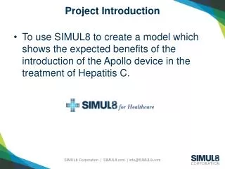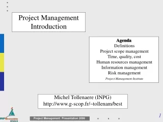

Project Introduction
E N D
Presentation Transcript
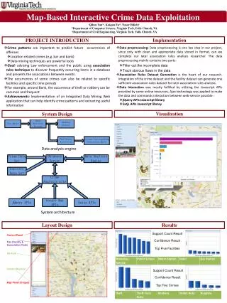
Project Introduction • New high-tech classroom and lab facility • Area : 30,000sq.ft. • Function • To provide a home for innovative courses that take a team based approach to problem solving and design. • Inhabitants of building should feel a part of surrounding environ. • Create a work environment that stresses collaborative achievement.
Project Constraints • Constrained site- limited by palm grove, existing buildings and sea • Budget - 5.5 million • Completed by 9/30/12 • Hurricane zone • Hot, humid climatic conditions; high heat loads • Structural system must withstand high winds and possible flooding • Floor height restrictions
Site Context - Seaside, Florida Seaside Florida provides a rich and colorful oceanfront community with a unique architectural sophistication. City/ Campus Plan Hybrid Building, Steven Holl
Design Concept 1 • Special architectural features • High heat load on east side • Solid auditorium structure • Inefficient floor plans
Design Concept 2 • Meets height requirements • Limited cranage space • Compact but awkward floor plans
Design Concept 3 • Light steel structure over flood protected “Core” Business • Inflexible architecture layout • Excessive use of concrete
Architecture View of Building from road
South Elevation South-east Axon First Floor Plan
West Elevation Second Floor Plan
North Elevation Third Floor Plan
East Elevation Section Through Auditorium
Area Analysis Entry Perspective
Interior Space Model First Floor View from Sea
Interior Space Model Second Floor
Interior Space Model Third Floor
Iterative Processes Problem: Design for 3rd floor office wing, elevated slab • Wayfinding problems caused by numerous corridors • Quality of space corrupted by low ceiling heights • Elevated slab raises several constructability issues • Prohibitive complexity for architectural and structural design
Iterative Processes Solution: Swap second and third floors entirely Large Classrooms Offices Auditorium • Walls to hide main Beams in • Large classrooms placed under • large open steel truss roofing • Simplified architectural design • Organized architectural design, faculty offices with exterior view
Iterative Processes Leveraging Aesthetic and Functional Concerns • Architect prefers tighter spacing of structural elements to improve asymmetric balance • Glazed corner important to design concept • Large shear walls block a great deal of window wall on North elevation
Structural System • Gravity loads • DL = 150 psf • LL = 50-100 psf • Wind load 120 psf • ASCE 7-95 • Preliminary system
Office Wing • Shear wall system • Foundation • 9 ‘ Flat slab perimeter beam
Gravity System • Beams • Cast in place 9”x12” (2.0%) • Columns • Custom precast 18”x18” (3%) / 20”x20” (3.5%) • Auditorium precast 26”x16” (1.5%) • Interior cast in Place 18”x18” (2%)
Auditorium • Retaining wall / slab • Precast columns • Glass corners • Roof ?
Lateral System Auditorium • Higher wind pressure • Shear wall connection • Ringbeam
Integrated Solution • Hidden steel beams W24x450 (90%) • Larger shear walls • Reduced cantilever
Equipment Crane - Link Belt Hydraulic Truck Crane - HTC 11100 Backhoe Loader - Caterpillar 426C
Comparison: Column Construction Precast Cast-in-place
Opportunities for Off-site Fabrication • Copper roof • Auditorium Roof Truss • Precast concrete columns • Curtain wall and cladding frame
Design Analysis • Location a factor in team dynamics • Tight design process between engineer and architect • Design process monitored by construction management
Collaborative Successes Strong integration of structure and architecture Friendly relationship, friendly struggles Programmatic goals achieved through iterative design process Collaborative Inadequacies Lack of shared product model Creation of numerous design models, several for each discipline Difficulties with communicating key structural concerns Group Assessment
Using Technology Collaborative Means Heavy use of web based technologies • NetMeeting • Email • Discussion Forums • Group web space • Technology cannot offset lack of communication • Learning new technologies requires time overhead and may not produce desired results
Lessons learned • Everyone should use compatible technology • Shared product model saves time and increases efficiency across disciplines • Team should follow protocols for developing and sharing information • Greater understanding of other disciplines needs • If technology is used properly, time and effort are saved for the entire team