Download
1 / 27
270 likes | 403 Vues
This paper discusses the advancements in Raman amplification within the petawatt regime, focusing on pulse compression techniques in plasma. High-intensity laser pulses can achieve remarkable output by utilizing Raman scattering to compress long pulse durations into shorter, more powerful pulses. Key challenges include managing instabilities and energy transfer efficiencies, as well as the balance between plasma density and intensity. The authors provide a comprehensive overview of experimental campaigns, simulations, and the underlying physics, providing insights into the future of high-intensity laser applications.

E N D
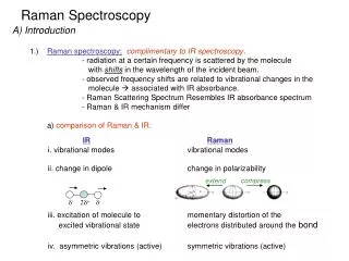
Efficient Raman amplification into the petawatt regime • Raoul Trines • Frederico Fiúza • R.A. Fonseca, L.O. Silva, R. Bingham,A. Cairns, P. Norreys R. Trines, F. Fiúza et al., Nature Physics, DOI: 10.1038/NPHYS1793 (2010)
Background • Pulse compression in plasma, or: making an instability work for you • Why pulse compression in plasma? • Solid optics: max. intensity 1012 W/cm2 • Plasma: max. intensity 1017 W/cm2 [1,2] • Promises: • Visible light: 1025 – 1027 W/cm2 [3,4] • X-rays: 1029 W/cm2 [5] [1] G. Shvetset al., Phys. Rev. Lett. 81, 4879 (1998). [2] V.M. Malkinet al., Phys. Rev. Lett. 82, 4448 (1999). [3] Fisch & Malkin, PoP10, 2056 (2003). [4] Malkin & Fisch, PoP12, 044507 (2005). [5] Malkin, Fisch & Wurtele, PRE 75, 026404 (2007).
How it works • A long laser pulse (pump) in plasma will spontaneously scatter off Langmuir waves: Raman scattering Stimulate this scattering by sending in a short, counter propagating pulse at the frequency of the scattered light (probe pulse) Because scattering happens mainly at the location of the probe, most of the energy of the long pump will go into the short probe: efficient pulse compression
Miniature pulse compressor Solid state compressor (Vulcan) Volume of a plasma-based compressor Image: STFC Media Services
A brief history • 1998-99: First papers by Shvets, Fisch, Pukhov, Malkin (Princeton) • 2001-02: First dedicated PIC development and simulations (XOOPIC at UC Berkeley) • 2003-10: 2-D full-PIC abandoned in favour of 1-D PIC with averaged fields, or 1-D fluid codes • 2004-10: Experimental campaign at Princeton • 2007-10: Experimental campaign at Livermore • Actively being studied by many groups: Princeton, LLNL, UCB, U. Strathclyde, U. Bordeaux, South Korea, LANL, Taiwan...
Current status • Theory: mostly linear, for low intensities, 1-D, no regard for instabilities like RFS and filamentation • Numerics: envelope models, 1-D fluid/particles • Best experiment: 2.3*1014 W/cm2 pump → 2.5*1016 W/cm2, 15 μm wide probe: 60 GW [6] • Why the difference between promises and results? [6] J. Renet al., Nature Physics 3, 732 (2007).
Simulations • We need large-scale 2-D/3-D PIC simulations to find out what is going on • We have performed 1-D and 2-D PIC simulations using the codes XOOPIC (UC Berkeley, [7]) and OSIRIS (UCLA and IST Lisbon, [8]) • Results in similar situations were used to mutually verify the codes • We used a wide moving window in 2-D XOOPIC and a narrow static window in 2-D OSIRIS, so the simulations complement each other. • We gratefully acknowledge UC Berkeley and the Osiris Consortium for the use of their codes • We are grateful to RAL Didcot, IST Lisbon and UCLA for the use of their parallel computing facilities [7] J.P. Verboncoeuret al., Comp. Phys. Comm. 87, 199 (1995). [8] R. Fonseca et al.,Lect. Notes Comput. Sci. 2331, 342 (2002).
Overview of results ω0/ωp Intensity (W/cm2) For each combination of pump intensity and ω0/ωp, either the maximum reached probe intensity is listed in W/cm2, or the reason for failure (probe Raman forward scatter, probe filamentation, inefficient energy transfer from pump to probe) It is simply very hard to get it right!
Issues • Instability as foundation for pulse compression... Doesn’t that become unstable? • The four horsemen of the Apocalypse: • Probe filamentation • Probe Raman forward scattering • Inefficient energy transfer • Saturation
Filamentation 2-D and 3-D Osiris simulations of the central part of the probe, by F. Fiuza Transverse filamentation in 2-D,apump = 0.03 (red) or 0.1 (blue) Transverse filamentation in 3-D,apump = 0.03, both directions Filamentation can be kept in check if both the pump intensity and plasma density are not too high
Probe RFS • Probe Raman forward scatter occurs when either the plasma density or the pump intensity is too high and will give the probe a poor longitudinal envelope probe RFS for intense pump probe RFS for high density Ey Ex x (m) Pump: I=2*1014 W/cm2 n0 = 1.75*1019 cm-3 (ω0/ωp = 10) Pump: I=2*1015 W/cm2 or I=2*1016 W/cm2 ω0/ωp = 20
Efficiency versus density • Low plasma density: energy transfer is inefficient • High plasma density: instabilities destroy probe • Stick to middle ground: ω0/ωp = 14-20 Pump intensity before and after seed; a0=0.01; a1=0.1; ω0/ωp = 10, 20, 40; after 1 mm rel. pump intensity seed x1 (m)
Saturation • Probe growth will saturate: • Probe RFS; probe also generates a wakefield • Probe limited to 300-1000 times pump • Higher pump intensity yields higher absolute growth but lower relative growth Superradiantampl. Raman amplification a12/2 s (mm) red: high density (1019 cm-3) → saturation black: low density (1018 cm-3) → poor energy transfer seed: 50 fs, a1 = 0.1; pump a0=0.1; n0 = 1.75*1019 cm-3
Simulations versus theory • RBS growth increases with pump amplitude and plasma density, but so do pump RFS and probe filamentation • Optimal simulation regime corresponds to at most 10 e-foldings for pump RFS and probe filamentation Growth versus plasma density Growth versus pump amplitude
Bonus issue: pump stability • Pump beam must travel through plasma column before it meets the probe, and may go unstable: RBS, RFS, modulation, filamentation... • Two movies by F. Fiúza will illustrate this • Pump with I = 1015 or 1016 Wcm-2 will propagate though 4 mm plasma with ω/ωp = 20 • At the higher intensity, the pump is so unstable that the probe does not even amplify properly Pump filamentation, a0 = 0.1; ω0/ωp = 20; after 2.5 mm
A bad result For a 2*1015 W/cm2 pump and ω0/ωp = 10, the probe is still amplified, but also destroyed by filamentation
A good result For a 2*1015 W/cm2 pump and ω0/ωp = 20, the probe is amplified to 8*1017 W/cm2 after 4 mm of propagation, with limited filamentation 10 TW → 2 PW and transversely extensible!
Focusability focused envelope for ‘spiky’ pulse focused envelope for smooth pulse Smooth pulse can be focused to 2.3 times the bandwidth limit. A 200 PW pulse with 1 cm diameter could be focused to 1025 Wcm-2.
What next? • Limit pump length to ~25 ps (compression ration 1:1000), to avoid saturation and instabilities • Fairly low density, ω/ωp ~ 14-20 • Not too intense pump: 1014 -1015 W/cm2 • acceptable efficiency (25-30%) • no RFS or filamentation yet • Wide pulses, 1 mm or more • Need to move away from “classical” parameter regime
Scalability Everything scales with pump wave length λ0!
Raman at different wave lengths • Microwave experiments • EISCAT radar beam experiments • X-ray amplification (see also talk by B. Bingham)
EISCAT Raman amplification Scale everything up to use cm or metre wave lengths – space is big enoughSpace plasma is the “best” plasma: large plasma parameter, no collisionsProposal submitted to EISCAT and granted time on the facilities, spring 2011
EISCAT Raman amplification Figure 1: Counter-propagating HF Heater and Dynasonde pulses exchange energy by Raman amplification, producing a short, powerful Heater pulse at the Dynasonde frequency.
EISCAT Raman amplification Figure 2: Co-propagating Heater and Dynasonde pulses produce a Langmuir “beat wave”, capable of heating or accelerating the plasma.
Conclusions • Extending Raman amplification to reach truly high output intensities is possible for the right parameters • Beware of the four horsemen: filamentation, RFS, inefficiency, saturation • Amplification of wide probes to petawatt level is within reach • Everything scales with pump wave length, so also works for X-rays: attosecond X-ray pulses possible