Mechanics
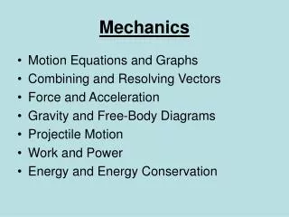
Mechanics. One of the most important fields in engineering. General Areas. Some Courses at FIU. Mechanical Engineering Curriculum EGN 3311 Statics EGN 3321 Dynamics EGN 3365 Materials in Engineering EMA 3702 Mechanics and Material Science EMA 3702L Mechanics and Materials Science Lab

Mechanics
E N D
Presentation Transcript
Mechanics One of the most important fields in engineering
Some Courses at FIU • Mechanical Engineering Curriculum • EGN 3311 Statics • EGN 3321 Dynamics • EGN 3365 Materials in Engineering • EMA 3702 Mechanics and Material Science • EMA 3702L Mechanics and Materials Science Lab • EML 4702 Fluid Dynamics • EML 4711 Gas Dynamics
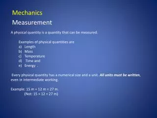
Scalars and Vectors • A scalar is a quantity having magnitude, but no direction. Having magnitude only a scalar may be positive or negative. but has no directional characteristics. • Common scalar quantities are length, mass, temperature, energy, volume, and density. • A vector is a quantity having both magnitude and direction. A vector may be positive or negative and has a specified direction in space. Common vector quantities are displacement, force, velocity, acceleration, stress, and momentum. • A scalar quantity can he fully defined by a single parameter, its magnitude, whereas a vector requires that both its magnitude and direction be specified.
Vector Components • Express: • Components • Magnitudes • Sum • Magnitude of Sum
Unit Vectors • Express: • Components • Magnitudes • Sum • Magnitude of Sum
Example • Two vectors have magnitudes of A = 8 and B = 6 and directions as shown in the figure • Find the resultant vector, using • The parallelogram law and • By resolving the vectors into their x andy components.
Example • For the vectors: • A = 3i- 6i + k • B = 5i + j – 2k • C =-2i + 4j + 3k • Find the resultant vector and its magnitude.
Forces • To the engineer, force is defined as an influence that causes a body to deform or accelerate. For example: • Push • Pull • Lift • When the forces acting on a body are unbalanced, the body undergoes an acceleration. For example: • The propulsive force delivered to the wheels of an automobile can exceed the frictional forces that tend to retard the automobile’s motion so the automobile accelerates • Similarly. the thrust and lift forces acting on an aircraft can exceed the weight and drag forces, thereby allowing the aircraft to accelerate vertically and horizontally.
Forces • Forces commonly encountered in the majority of engineering systems may be generally categorized as: • A contact force • Gravitational force • Cable force • Pressure force, or • fluid dynamic force
Forces Forces are vectors, so all the mathematical operations and expressions that apply to vectors apply to forces
Forces • Three coplanar forces act as shown in the figure. Find the resultant force, its magnitude and its direction with respect to the positive x-axis.
Stabilizing a Communications Tower with Cables • Tall slender structures often incorporate cables to stabilize them. • The cables, which are connected at various points around the structure and along its length. are connected to concrete anchors buried deep in the ground. • Shown in Figure 4.16(a) is a typical communications tower that is stabilized with several cables On this particular tower each ground anchor facilitates two cables that are connected at a common point, as shown in Figure 4.16(b). • The upper and lower cables exert forces of 15 kN and 25 kN respectively. and their directions are 45 and 32 respectively, as measured from the ground (Figure 4.16(c)). What is the resultant force exerted by the cables on the ground anchor?
FREE-BODY DIAGRAMS • A free-Body diagram is a diagram that shows all external forces acting on the body. As the term implies, a free-body diagram shows only the body in question, being isolated or “free” from all other bodies • The body is conceptually removed from all: • supports • connections, and • regions of contact with other bodies • All forces produced by these external influences are schematically represented on the free- body diagram.
Procedure for Constructing Free-Body Diagrams • The following procedure should be followed when constructing free-body diagrams: • Identify the body you wish to isolate and make a simple drawing of it. • Draw the appropriate force vectors at all locations of supports, connections and contacts with other bodies • Draw a force vector for the weight of the body, unless the gravitational force is to he neglected in the analysis. • Label all forces that are known with a numerical value and those that are unknown with a letter. • Draw a coordinate system on. or near, the tree-body to establish directions of the forces
A body is in static or dynamic equilibrium if the vector sum of all external forces is zero. Consistent with this definition, the condition of equilibrium may be stated mathematically as:
More Complex Truss http://www.jhu.edu/~virtlab/bridge/bridge.htm
Stress • Stress is used to: • To determine if a certain structure can withstand the forces applies to I • To compare different materials
Stress • This mathematical definition of normal stress is actually an average normal stress, • because there may be a variation of stress across the cross section of the bar. • Stress variations are normally present only near points where the external forces are applied however. • The stress equation may he used in the majority of stress calculations without regard to stress variations.
Strain • : strain Strain is dimensionless but sometimes can be expressed in mixed units like m/m
Hooke’s Law • The second equation is another form (More useful for Material Engineering) of Hooke’s Law • E: modulus of Elasticity or Young’s Module, obtained experimentally • : stress • : strain
Homework • For the following homework problems, use the general analysis procedure of • Problem Statement • Diagram. • Assumptions • governing equations • Calculations • Solution check • Discussion
Homework • A 250-kg cylinder rests in a long channel as shown. Find the forces acting on the cylinder by the sides of the channel.
Homework • A 200 kg engine block hangs from a system of cables as shown in the Figure. Find the tension in cables AB and AC. Cable AB is horizontal.
Homework • A 200-kg engine block hangs from a system of cables as shown in the Figure. Find the Normal Stress and Axial Deformation in cables AB and AC. The cables are 0.7m long and have a diameter of 4 mm. The cables are steel with a modulus of elasticity of E = 200 GPa.
Homework • Tall slender structures often incorporate cables to stabilize them. • The cables, which are connected at various points around the structure and along its length. are connected to concrete anchors buried deep in the ground. • Shown in Figure (a) is a typical communications tower that is stabilized with several cables On this particular tower each ground anchor facilitates two cables that are connected at a common point, as shown in Figure 6(b). • The upper and lower cables exert forces of 15 kN and 25 kN respectively. and their directions are 45 and 32 respectively, as measured from the ground (Figure (c)). What is the resultant force exerted by the cables on the ground anchor?